Simultaneous Detection of Caspase-8 and Caspase-3 Activity with AIEgens: A Guide for Advanced Apoptosis Imaging
This article provides a comprehensive resource for researchers and drug development professionals on the simultaneous detection of caspase-8 and caspase-3 activity using aggregation-induced emission fluorogens (AIEgens).
Simultaneous Detection of Caspase-8 and Caspase-3 Activity with AIEgens: A Guide for Advanced Apoptosis Imaging
Abstract
This article provides a comprehensive resource for researchers and drug development professionals on the simultaneous detection of caspase-8 and caspase-3 activity using aggregation-induced emission fluorogens (AIEgens). It covers the foundational biology of caspase cascades in apoptosis, details the design and working mechanism of a novel single fluorescent probe that targets both enzymes, and explores its applications in real-time monitoring of cell death for evaluating anticancer drug efficacy. The content further addresses critical troubleshooting and optimization strategies for probe use, validates the methodology against other techniques, and discusses its significant implications for advancing biomedical research and therapeutic screening.
Caspase Cascades and the AIEgen Advantage: Foundational Concepts for Simultaneous Detection
The Hierarchical Roles of Caspase-8 and Caspase-3 in Apoptotic Signaling Pathways
Apoptosis, or programmed cell death, is a fundamental biological process crucial for maintaining tissue homeostasis and eliminating damaged cells [1]. The caspase family of cysteine proteases serves as the central executioners of apoptosis. Within this family, caspase-8 functions as a key initiator in the extrinsic apoptotic pathway, while caspase-3 acts as a primary executioner in the final stages of cell death [2] [1]. Understanding the hierarchical relationship and activation kinetics between these two enzymes is essential for both basic biological research and the development of novel therapeutic strategies, particularly in oncology [2] [1].
Traditional methods for detecting caspase activity, including antibody-based techniques like Western blotting, provide fundamental insights but are limited to endpoint analyses and lack the temporal resolution needed to capture rapid activation kinetics in living systems [2]. The emergence of novel fluorescent probes, particularly those utilizing aggregation-induced emission luminogens (AIEgens), has revolutionized our ability to monitor caspase activities in real-time within live cells [3]. This application note details experimental protocols leveraging an innovative AIEgen-based probe for the simultaneous detection of caspase-8 and caspase-3 activities, providing researchers with a powerful tool to dissect the apoptotic cascade.
Background
The Apoptotic Signaling Cascade
Apoptosis proceeds through two primary pathways: the extrinsic (death receptor) pathway and the intrinsic (mitochondrial) pathway. Caspase-8 is a crucial initiator caspase in the extrinsic pathway, activated upon ligation of death receptors such as Fas on the cell surface [1]. Once activated, caspase-8 can directly cleave and activate executioner caspases, including caspase-3 [1] [4]. Caspase-3 then orchestrates the systematic dismantling of the cell by cleaving numerous structural and regulatory proteins [1] [5].
The hierarchical relationship between these caspases forms a proteolytic cascade, where caspase-8 activation precedes and triggers caspase-3 activation [3] [4]. This sequential activation pattern provides a unique opportunity for monitoring apoptosis progression through simultaneous detection of both enzymes.
Key Characteristics of Caspase-8 and Caspase-3
Table 1: Key Characteristics of Caspase-8 and Caspase-3
| Feature | Caspase-8 | Caspase-3 |
|---|---|---|
| Role in Apoptosis | Initiator Caspase | Executioner Caspase |
| Activation Pathway | Extrinsic (Death Receptor) | Common to both Extrinsic and Intrinsic |
| Primary Substrates | Caspase-3, Bid, RIPK1 | PARP, ICAD, Structural Proteins |
| Activation Mechanism | Dimerization and auto-cleavage at specific aspartic residues (e.g., D387) [6] | Proteolytic cleavage by initiator caspases including caspase-8 [4] |
| Cleavage Motif | IETD [3] [7] | DEVD [8] [5] |
| Activation Kinetics | Rapid, complete within minutes once initiated [4] [8] | Very rapid (≤5 minutes) following initiator caspase activation [8] |
Experimental Principles and Design
AIEgen-Based Detection Strategy
The protocol centers on a unique dual-signal fluorescent probe that incorporates two AIEgens with distinctive emission profiles: a green-emitting tetraphenylsilole (TPS) derivative and a red-emitting TPETH moiety [3]. These fluorogens are connected by a hydrophilic peptide substrate (DVEDIETD) containing specific cleavage sites for caspase-8 (IETD) and caspase-3 (DVED) [3].
The probe operates on the principle of aggregation-induced emission (AIE), where the fluorogens are non-emissive in aqueous media but become highly fluorescent upon aggregation. In its intact state, the hydrophilic peptide keeps the probe molecularly dissolved in aqueous environments, resulting in minimal background fluorescence. During apoptosis, sequential cleavage by activated caspases releases the hydrophobic AIEgens, which then aggregate in the cellular environment, triggering a dramatic fluorescence turn-on [3].
Probe Design and Activation Mechanism
Table 2: Components of the Dual-Signal AIEgen Probe
| Component | Structure/Sequence | Function | Optical Properties |
|---|---|---|---|
| Green AIEgen | TPS-N3 (Tetraphenylsilole derivative) | Reports caspase-8 activity | Emission maximum at 480 nm (green) upon excitation at 405 nm [3] |
| Red AIEgen | TPETH-Mal | Reports caspase-3 activity | Emission maximum at 650 nm (red) upon excitation at 405 nm [3] |
| Peptide Linker | DVEDIETD | Contains cleavage sites for both caspases | Caspase-8 cleaves at IETD, caspase-3 cleaves at DVED [3] |
| Overall Probe | TPETH–DVEDIETD–TPS | Non-fluorescent in aqueous solution, fluoresces upon caspase-mediated cleavage | Sequential green then red fluorescence turn-on [3] |
Materials and Equipment
Research Reagent Solutions
Table 3: Essential Reagents and Materials
| Item | Specifications/Description | Primary Function in Protocol |
|---|---|---|
| AIEgen Probe | TPETH–DVEDIETD–TPS (lyophilized powder) | Simultaneous detection of caspase-8 and caspase-3 activities [3] |
| Cell Line | HeLa cells (or other appropriate apoptotic model) | Apoptosis model system [3] |
| Apoptosis Inducer | Hydrogen peroxide (H₂O₂) [3] or Staurosporine [8] | Induction of extrinsic or intrinsic apoptosis |
| Caspase Inhibitors | Z-IETD-FMK (caspase-8 inhibitor), Z-DEVD-FMK (caspase-3 inhibitor) [3] | Specific inhibition of respective caspases for control experiments |
| Imaging Buffer | Phenol-red free culture medium or PBS | Maintenance of cell viability during imaging |
| DMSO | Molecular biology grade | Solvent for preparing probe stock solution |
| Fluorescence Microscope | Confocal or widefield system with 405 nm laser line and appropriate filter sets | Detection of green and red fluorescence signals |
Protocol
Probe Preparation and Cell Treatment
Probe Stock Solution Preparation
- Prepare a 1 mM stock solution of the AIEgen probe (TPETH–DVEDIETD–TPS) in anhydrous DMSO.
- Aliquot and store at -20°C protected from light.
Cell Culture and Seeding
- Culture HeLa cells in appropriate medium (DMEM with 10% FBS) at 37°C in 5% CO₂.
- Seed cells into 35 mm glass-bottom imaging dishes at 60-70% confluence 24 hours before experimentation.
Apoptosis Induction and Probe Loading
- Prepare working solution of the probe by diluting the stock solution in culture medium to a final concentration of 10 µM.
- Induce apoptosis by treating cells with 100-500 µM hydrogen peroxide (H₂O₂) [3].
- Simultaneously add the 10 µM probe working solution to the cells.
- Include appropriate control groups:
- Untreated cells with probe
- Cells pre-treated with 20 µM Z-IETD-FMK (caspase-8 inhibitor) for 1 hour before induction and probe addition
- Cells pre-treated with 20 µM Z-DEVD-FMK (caspase-3 inhibitor) for 1 hour before induction and probe addition
Real-Time Imaging and Data Acquisition
Microscope Setup
- Set up live-cell imaging system with environmental chamber maintained at 37°C and 5% CO₂.
- Configure excitation source at 405 nm and appropriate emission filters for green (480/40 nm) and red (650/40 nm) channels.
- Set imaging interval to 5 minutes for kinetic analysis of caspase activation.
Time-Lapse Imaging
- Begin time-lapse imaging immediately after probe addition and apoptosis induction.
- Acquire images from both fluorescence channels at each time point for 3-6 hours.
- Include brightfield images to monitor morphological changes associated with apoptosis.
Data Extraction and Analysis
- Use image analysis software (e.g., ImageJ) to quantify fluorescence intensities in both channels.
- Define regions of interest (ROIs) around individual cells and measure mean fluorescence intensity for each channel over time.
- Calculate normalized fluorescence intensity (F/F₀) where F₀ represents baseline fluorescence at time zero.
Validation Experiments
Specificity Validation
- Perform control experiments with caspase-specific inhibitors to confirm that fluorescence activation is caspase-dependent.
- Compare fluorescence kinetics between inhibitor-treated and non-inhibited cells.
Dose-Response Analysis
- Treat cells with varying concentrations of apoptosis inducers (e.g., 0, 50, 100, 200, 500 µM H₂O₂).
- Quantify the rate and magnitude of fluorescence turn-on for both channels to establish correlation with apoptosis intensity.
Expected Results and Interpretation
Fluorescence Kinetics and Caspase Activation
The typical experimental results will demonstrate a sequential fluorescence turn-on, with green fluorescence (caspase-8 activation) preceding red fluorescence (caspase-3 activation) by approximately 30-60 minutes [3]. This temporal pattern reflects the hierarchical relationship between these caspases in the apoptotic signaling pathway.
Table 4: Expected Kinetic Parameters for Caspase Activation
| Parameter | Caspase-8 (Green Signal) | Caspase-3 (Red Signal) |
|---|---|---|
| Onset Time | 30-60 minutes post-induction [3] | 60-90 minutes post-induction [3] |
| Time to Peak | 90-120 minutes [3] | 120-150 minutes [3] |
| Fold Increase | ~110-fold over baseline [3] | Significant intensification, specific fold not reported [3] |
| Inhibition Efficacy | >90% reduction with Z-IETD-FMK [3] | >90% reduction with Z-DEVD-FMK [3] |
At the single-cell level, caspase activation is remarkably rapid once initiated, with complete activation occurring within 5 minutes or less [8]. However, within a cell population, individual cells initiate apoptosis at different times, creating an asynchronous response that appears more gradual in population-level analyses [8] [9].
Data Interpretation Guidelines
- Sequential Green-Red Fluorescence: Confirms canonical apoptotic pathway with caspase-8 activation preceding caspase-3.
- Green Fluorescence Only: Suggests incomplete apoptosis or specific caspase-8 activation without full execution phase.
- Red Fluorescence Only: May indicate alternative activation pathways bypassing caspase-8.
- No Fluorescence Activation: Suggests absence of apoptosis or ineffective induction.
- Inhibitor Abolishment of Signal: Validates caspase-specific nature of the fluorescence signal.
Troubleshooting
| Issue | Potential Cause | Solution |
|---|---|---|
| High Background Fluorescence | Probe aggregation in solution | Ensure proper preparation of stock solution and use fresh dilutions in aqueous buffer |
| Weak Signal | Insufficient apoptosis induction or probe concentration | Optimize inducer concentration; confirm cell responsiveness; increase probe concentration up to 20 µM |
| No Sequential Activation | Overwhelming apoptotic stimulus causing simultaneous activation | Titrate inducer to lower concentrations; use milder apoptosis inducers |
| Signal in Control Cells | Spontaneous apoptosis or probe toxicity | Include viability controls; reduce probe concentration if cytotoxic |
| Poor Channel Separation | Spectral bleed-through | Optimize filter sets; perform sequential rather than simultaneous channel acquisition |
Applications and Significance
The simultaneous detection of caspase-8 and caspase-3 activities using this AIEgen-based approach provides significant advantages for apoptosis research:
- High-Sensitivity Drug Screening: Enables evaluation of chemotherapeutic efficacy by monitoring caspase activation in real-time [3].
- Kinetic Analysis of Apoptotic Pathways: Allows precise determination of activation hierarchies and temporal relationships between different caspases.
- Single-Cell Heterogeneity Studies: Facilitates investigation of cell-to-cell variability in apoptotic response [9].
- Mechanistic Studies: Useful for delineating specific apoptotic pathways activated by different stimuli.
- Therapeutic Development: Supports screening for novel compounds that modulate specific caspase activities.
This protocol represents a significant advancement over traditional caspase detection methods by enabling multiplexed, real-time monitoring of multiple caspase activities in live cells with minimal background fluorescence, providing unprecedented temporal resolution of apoptotic signaling events.
Visualizations
Aggregation-Induced Emission (AIE) represents a paradigm shift in fluorescence technology, offering a solution to the longstanding challenge of aggregation-caused quenching (ACQ) that plagues conventional fluorophores. This application note explores the fundamental principles of AIE and its exceptional suitability for sensing caspase activity in biological systems. We detail a specific protocol for simultaneously monitoring caspase-8 and caspase-3 activation during apoptosis using a single AIE-based probe, providing researchers with a robust methodology for real-time, multiplexed enzyme activity tracking. The AIE approach enables high signal-to-background ratio, superior photostability, and dual-signal output for self-validated detection, making it particularly valuable for drug screening and therapeutic efficacy assessment.
Fundamental Principles
Aggregation-Induced Emission (AIE) is a photophysical phenomenon in which certain organic luminophores exhibit enhanced light emission in their aggregated or solid state compared to their solution state [10]. This behavior directly contrasts with conventional fluorophores, which typically suffer from aggregation-caused quenching (ACQ) due to excessive π-π stacking interactions in concentrated or aggregated states [11]. The discovery of AIE by Tang et al. in 2001 opened new avenues for fluorescence-based sensing and bioimaging applications where high local concentrations are inevitable [11].
The primary mechanism responsible for AIE is the Restriction of Intramolecular Motion (RIM) [3] [12]. In solution, AIE luminogens (AIEgens) can undergo significant intramolecular rotations and vibrations, which dissipate excited-state energy through non-radiative pathways. When these molecules aggregate, physical restrictions imposed by the crowded environment suppress these motions, effectively closing the non-radiative channels and opening radiative pathways, resulting in strong fluorescence emission [12]. This mechanistic understanding has been further refined through the Control of Conical Intersection Accessibility (CCIA) model, which describes how restricting access to conical intersections on potential energy surfaces enables enhanced fluorescence in the aggregated state [12].
AIE vs. Conventional Fluorophores
Table 1: Comparison between AIEgens and Conventional Fluorophores
| Property | AIEgens | Conventional Fluorophores |
|---|---|---|
| Emission in Aggregate State | Enhanced | Quenched (ACQ) |
| Signal-to-Background Ratio | High | Low to Moderate |
| Photostability | High | Variable, often prone to photobleaching |
| Stokes Shift | Large | Small to Moderate |
| Quantitation in Bioassay | Excellent via "turn-on" mode | Challenging due to ACQ |
| Multiplexing Capability | Favorable due to large Stokes shifts | Limited by spectral overlap |
AIE-Based Caspase Sensing: Mechanism and Design
Caspases as Apoptosis Biomarkers
Caspases, a family of cysteine-aspartic proteases, play critical roles in programmed cell death (apoptosis) and inflammation [13]. Among these, caspase-3 serves as a key executioner protease that is activated in both intrinsic and extrinsic apoptotic pathways, while caspase-8 functions as an initiator caspase in the extrinsic pathway [3]. The sequential activation of these enzymes forms a cascade that ultimately leads to cell death, making them valuable biomarkers for monitoring apoptosis, particularly in cancer research and therapeutic efficacy assessment [3] [13].
AIE Probe Design for Caspase Detection
The fundamental design of AIE-based caspase probes leverages the unique photophysics of AIEgens coupled with enzyme-specific peptide substrates. A representative probe for simultaneous caspase-8 and caspase-3 detection consists of three key components [3]:
- Two AIE fluorogens with distinct emission profiles (e.g., green and red) but excitable at a single wavelength
- A hydrophilic peptide substrate containing specific cleavage sites for both caspase-8 (IETD) and caspase-3 (DEVD)
- Linker chemistry connecting the AIEgens to the peptide substrate
In aqueous media, the probe remains molecularly dissolved and non-fluorescent due to free intramolecular motions of the AIEgens. Upon caspase activation and subsequent cleavage of the peptide substrate, hydrophobic AIEgen residues are released, leading to aggregation and dramatic fluorescence turn-on [3] [14].
Figure 1: AIE Caspase Sensing Mechanism
Protocol: Simultaneous Detection of Caspase-8 and Caspase-3 Activity
Probe Synthesis and Characterization
Materials:
- Azide-functionalized tetraphenylsilole (TPS-N3) for green emission
- Maleimide-functionalized TPETH (TPETH-Mal) for red emission
- Peptide substrate (CDVEDIETDPra) containing caspase-8 (IETD) and caspase-3 (DEVD) cleavage sites
- HPLC purification system
- DMSO and PBS buffer
Synthesis Procedure:
- Perform click chemistry between TPS-N3 and CDVEDIETDPra to yield CDVEDIETD-TPS with a terminal thiol group [3].
- React the thiol-terminated intermediate with TPETH-Mal to form the final probe (denoted as Probe 1) [3].
- Purify using preparatory HPLC and characterize via NMR and mass spectrometry [3].
- Confirm AIE properties by analyzing PL spectra in DMSO/water mixtures with increasing water fractions (fw = 0-99%) [3].
In Vitro Caspase Activity Assay
Materials:
- Purified caspase-3 and caspase-8 enzymes
- Caspase inhibitors (Z-IETD-FMK for caspase-8, Z-DEVD-FMK for caspase-3)
- DMSO/PBS buffer (1:99 v/v)
- Fluorescence spectrophotometer
Procedure:
- Prepare probe solution (1 μM) in DMSO/PBS buffer (1:99 v/v) [3].
- Record baseline fluorescence with excitation at 405 nm, collecting emission at 480 nm (green, TPS) and 650 nm (red, TPETH) [3].
- Add caspase-8 (0-200 pM) and incubate at 37°C for 0-60 minutes.
- Monitor green fluorescence enhancement at 480 nm corresponding to caspase-8 activity [3].
- For caspase-3 detection, add caspase-3 (0-200 pM) to separate probe aliquots and incubate at 37°C for 0-60 minutes.
- Monitor red fluorescence enhancement at 650 nm corresponding to caspase-3 activity [3].
- For inhibition controls, pre-treat caspase enzymes with specific inhibitors for 30 minutes before adding to probe solution [3].
Table 2: Quantitative Detection Parameters for AIE-based Caspase Sensing
| Parameter | Caspase-8 (Green Signal) | Caspase-3 (Red Signal) |
|---|---|---|
| Detection Limit | Linear range to 200 pM | Linear range to 200 pM |
| Signal Enhancement | 110-fold increase at fw = 99% | Significant intensity increase |
| Time to Saturation | ~60 minutes | ~60 minutes |
| Michaelis Constant (K M) | 5.40 μM | Similar range expected |
| Selectivity | No cross-reactivity with other caspases | No cross-reactivity with other caspases |
Cellular Apoptosis Imaging
Materials:
- HeLa cell line
- Apoptosis inducer (hydrogen peroxide, anticancer drugs)
- Cell culture medium
- Confocal microscopy system
Procedure:
- Culture HeLa cells in appropriate medium and seed onto glass-bottom dishes [3].
- Induce apoptosis by treating with hydrogen peroxide (500 μM) or anticancer drugs (e.g., doxorubicin) [3] [15].
- Incubate with AIE probe (1 μM) for 1-2 hours at 37°C [3].
- Image using confocal microscopy with 405 nm excitation, collecting green (500-550 nm) and red (600-700 nm) channels simultaneously [3].
- Observe sequential fluorescence turn-on: green signal (caspase-8 activation) followed by red signal (caspase-3 activation) [3].
- Quantify fluorescence intensity over time to monitor caspase cascade kinetics.
Figure 2: Caspase Cascade Activation Pathway
The Scientist's Toolkit: Essential Research Reagents
Table 3: Key Research Reagent Solutions for AIE-based Caspase Sensing
| Reagent | Function | Application Notes |
|---|---|---|
| TPS-N3 | Green-emitting AIEgen | Azide-functionalized for click chemistry; emission at 480 nm [3] |
| TPETH-Mal | Red-emitting AIEgen | Maleimide-functionalized for thiol coupling; emission at 650 nm [3] |
| CDVEDIETDPra Peptide | Dual caspase substrate | Contains IETD (caspase-8) and DEVD (caspase-3) cleavage sites [3] |
| Z-IETD-FMK | Caspase-8 inhibitor | Specific inhibitor for control experiments [3] |
| Z-DEVD-FMK | Caspase-3 inhibitor | Specific inhibitor for control experiments [3] |
| HPLC Purification System | Probe purification | Essential for obtaining pure AIE probe before biological application [3] |
Advantages and Applications
Key Advantages of AIE for Caspase Sensing
The AIE-based approach offers several distinct advantages over traditional fluorescence methods for caspase detection:
High Signal-to-Background Ratio: The "turn-on" nature of AIE probes provides extremely low background fluorescence in aqueous media, with signal enhancements of up to 110-fold observed upon aggregation [3].
Dual Signal Output: The ability to incorporate multiple AIEgens with different emission colors but single-wavelength excitation enables multiplexed detection of multiple caspase activities simultaneously [3].
Superior Photostability: AIEgens exhibit enhanced resistance to photobleaching compared to conventional fluorophores, enabling long-term tracking of caspase activity [11].
Self-Validated Detection: The synchronous turn-on of dual fluorescence signals provides built-in validation, improving detection reliability [14].
Quantitative Capability: Linear correlation between fluorescence intensity and caspase concentration (R² = 0.97) enables accurate enzyme quantification [3].
Therapeutic Applications
The AIE-based caspase sensing platform has significant applications in biomedical research and drug development:
Anticancer Drug Screening: Real-time monitoring of caspase activation enables evaluation of therapeutic efficiency of anticancer drugs [3].
Apoptosis Mechanism Studies: Sequential activation of initiator and effector caspases can be tracked in live cells without interruption [13].
High-Throughput Screening: The robust signal output and simple operation make AIE probes suitable for screening caspase inhibitors or activators [13].
Therapeutic Efficacy Assessment: Caspase activation patterns can serve as biomarkers for treatment response in cancer therapy [3] [13].
Troubleshooting and Technical Considerations
Common Challenges and Solutions
Low Fluorescence Turn-On: Ensure proper aggregation conditions by maintaining high water fraction (>90%) in assay buffer. Verify peptide cleavage by HPLC and mass spectrometry [3].
Non-Specific Signal: Include appropriate inhibitor controls and validate specificity against other caspases and proteases [3].
Cellular Uptake Issues: For intracellular applications, consider incorporating cell-penetrating peptides or optimizing delivery methods [13].
Signal Variability: Standardize aggregation conditions and use internal references for quantification where necessary [3].
Future Perspectives
Recent advances in AIE research continue to expand applications for caspase sensing and beyond. Future developments may include:
- AIEgens with near-infrared emissions for deeper tissue imaging
- Activatable probes targeting inflammatory caspases involved in pyroptosis
- Integration with other detection modalities for multi-parameter analysis
- Point-of-care diagnostic devices leveraging AIE technology [11] [13]
The unique properties of AIE materials position them as powerful tools for deciphering cell death mechanisms and advancing drug discovery pipelines.
The Critical Need for Multiplexed Enzyme Activity Monitoring in Disease Diagnosis
Enzymes are crucial mediators in numerous physiological and pathological processes, with their activities serving as key indicators for understanding the progression of a variety of diseases including cancer, diabetes, and cardiovascular conditions [3]. Direct monitoring of enzyme activities within biological processes provides an effective approach for disease diagnosis and therapeutic evaluation. Biological events are often regulated by multiple enzymes acting in concert; for instance, in apoptosis, initiator and effector caspases function in a sequential cascade. Consequently, the ability to directly and simultaneously monitor multiple enzyme activities in a single process holds tremendous potential for advancing biological research and clinical diagnostics [3]. Traditional approaches utilizing multiple fluorescent probes with different emission colors encounter significant limitations including differential cellular uptake, distinct subcellular localization, and the requirement for multiple excitation wavelengths. This technical gap highlights the critical need for innovative sensing strategies that enable multiplexed enzyme monitoring within living cells.
AIEgen-Based Probes for Multiplexed Caspase Detection
Probe Design and Sensing Mechanism
Probe 1 (TPETH–DVEDIETD–TPS) represents a groundbreaking design in multiplexed enzyme sensing [3]. This single molecular probe integrates three key components:
- Two AIE fluorogens: A green-emitting tetraphenylsilole derivative (TPS) with an emission maximum at 480 nm and a red-emitting tetraphenylethylene derivative (TPETH) with an emission maximum at 650 nm. Both fluorogens are excitable at a single wavelength (405 nm) and exhibit aggregation-induced emission (AIE) characteristics.
- Hydrophilic peptide substrate: A specific peptide sequence (DVEDIETD) containing cleavage sites for both caspase-8 (IETD) and caspase-3 (DVED), serving as the recognition moiety.
The probe operates on a unique fluorescence activation mechanism. In aqueous media, the probe remains non-fluorescent due to the hydrophilic peptide maintaining the AIEgens in a molecularly dissolved state where intramolecular motions lead to non-radiative decay [3]. During apoptosis, initiator caspase-8 first cleaves at the IETD site, releasing the TPS moiety which aggregates due to its hydrophobicity, restricting intramolecular motions and activating green fluorescence. Subsequently, effector caspase-3 cleaves at the DVED site, releasing the TPETH moiety that similarly aggregates and activates red fluorescence. This sequential fluorescence turn-on enables real-time monitoring of the caspase cascade activation timeline within intact living cells.
Table 1: Optical Properties of AIEgens in Probe 1
| AIEgen Component | Absorption Maximum | Emission Maximum | Emission Color | Fluorescence Enhancement in Aggregated State |
|---|---|---|---|---|
| TPS-N3 | 360 nm | 480 nm | Green | 110-fold increase at f~w~ = 99% |
| TPETH-Mal | 430 nm (shoulder) | 650 nm | Red | Significant intensification with increased water fraction |
Experimental Validation and Characterization
The enzymatic response of Probe 1 was rigorously validated through controlled in vitro experiments. Upon incubation with caspase-8, the green fluorescence (480 nm) steadily intensified, reaching saturation after 60 minutes of incubation [3]. This fluorescence enhancement was directly attributed to the specific cleavage of the peptide substrate and subsequent aggregation of the TPS residues, confirmed through laser light scattering (LLS) and transmission electron microscope (TEM) analyses. The specificity of the response was demonstrated through inhibitor studies, where the fluorescence change was negligible in the presence of caspase-8 inhibitor (Z-IETD-FMK).
The quantitative capability of Probe 1 was established by treating the probe with different concentrations of caspase-8, which resulted in a linear correlation (R² = 0.97) between the fluorescence intensity at 480 nm and caspase-8 concentration [3]. Kinetic analysis revealed Michaelis constants (K~M~) of 5.40 μM and kinetic constants (k~cat~) of 1.39 s⁻¹, values comparable to those reported in previous studies. Selectivity testing confirmed that only caspase-8 treatment produced a significant increase in TPS fluorescence, with minimal response to other caspases or proteins.
Similarly, the red fluorescence channel responded specifically to caspase-3 activation, with fluorescence intensification prohibited by caspase-3 inhibitor (Z-DEVD-FMK) [3]. The probe maintained weak fluorescence across different ionic strength conditions and in cell culture medium, confirming its stability prior to enzymatic activation.
Application Notes & Protocols
Protocol: Monitoring Caspase Cascade in Apoptotic HeLa Cells
Objective: To monitor the sequential activation of caspase-8 and caspase-3 during hydrogen peroxide-induced apoptosis in HeLa cells using Probe 1.
Materials:
- Probe 1 (TPETH–DVEDIETD–TPS)
- HeLa cell line
- Hydrogen peroxide (H~2~O~2~) solution
- Cell culture medium and supplements
- Confocal microscopy imaging system with 405 nm excitation capability
- Fluorescence spectrometry capable of 405 nm excitation
Procedure:
- Cell Culture and Treatment:
- Culture HeLa cells in appropriate medium supplemented with 10% fetal bovine serum at 37°C in a 5% CO~2~ atmosphere.
- Seed cells into 35 mm glass-bottom culture dishes at a density of 1 × 10⁵ cells per dish and allow to adhere for 24 hours.
- Induce apoptosis by treating cells with 200 μM hydrogen peroxide for specified time points (0, 30, 60, 120, 180 minutes).
Probe Loading and Incubation:
- Prepare a 1 mM stock solution of Probe 1 in DMSO.
- Dilute the stock solution in serum-free culture medium to a final working concentration of 10 μM.
- After apoptosis induction, incubate cells with the Probe 1 working solution for 60 minutes at 37°C.
- Remove probe solution and wash cells twice with phosphate-buffered saline (PBS) to remove excess probe.
Fluorescence Imaging and Data Acquisition:
- Perform confocal microscopy imaging using a 405 nm laser for excitation.
- Collect green fluorescence emission between 500-550 nm for TPS signal (caspase-8 activity).
- Collect red fluorescence emission between 650-700 nm for TPETH signal (caspase-3 activity).
- Acquire time-lapse images every 15 minutes for 3 hours to capture the sequential activation cascade.
- Quantify fluorescence intensities using image analysis software (e.g., ImageJ) by measuring mean fluorescence intensity in regions of interest corresponding to individual cells.
Expected Results: In early apoptotic cells induced by hydrogen peroxide, green fluorescence (caspase-8 activity) should intensify first, followed by red fluorescence (caspase-3 activity), demonstrating the sequential cascade activation. The fluorescence turn-on ratio should exceed 100-fold compared to non-apoptotic control cells.
Protocol: Evaluating Anticancer Drug Efficacy
Objective: To utilize Probe 1 for evaluating the therapeutic efficiency of anticancer drugs based on their ability to induce caspase-mediated apoptosis.
Procedure:
- Drug Treatment:
- Seed HeLa cells in 96-well plates at a density of 1 × 10⁴ cells per well.
- Treat cells with varying concentrations of anticancer drugs (e.g., doxorubicin, cisplatin, paclitaxel) for 24 hours.
- Include untreated cells as negative control and cells treated with 200 μM hydrogen peroxide as positive control.
Caspase Activity Assessment:
- Incubate treated cells with 10 μM Probe 1 for 60 minutes at 37°C.
- Measure fluorescence intensities using a microplate reader with 405 nm excitation, 510/20 nm emission filter for green channel (caspase-8), and 670/20 nm emission filter for red channel (caspase-3).
- Calculate the ratio of activated cells based on fluorescence threshold determined from negative controls.
Data Analysis:
- Determine half-maximal inhibitory concentration (IC~50~) values based on caspase activation levels.
- Compare the timing and intensity of caspase-8 versus caspase-3 activation across different drug treatments.
- Correlate caspase activation patterns with drug mechanisms of action.
Table 2: Quantitative Analysis of Caspase Activation by Probe 1
| Parameter | Caspase-8 Detection | Caspase-3 Detection |
|---|---|---|
| Linear Range | Proportional to caspase-8 concentration | Responsive to caspase-3 concentration |
| Detection Sensitivity | Fluorescence enhancement with 60 min incubation | Fluorescence enhancement with caspase-3 cleavage |
| Specificity Confirmation | Inhibited by Z-IETD-FMK | Inhibited by Z-DEVD-FMK |
| Cellular Application | Activated in early apoptotic HeLa cells induced by H~2~O~2~ | Activated sequentially after caspase-8 in apoptotic cascade |
The Scientist's Toolkit: Research Reagent Solutions
Table 3: Essential Materials for AIEgen-Based Caspase Monitoring
| Reagent/Material | Function/Application | Specifications/Alternatives |
|---|---|---|
| Probe 1 (TPETH–DVEDIETD–TPS) | Primary sensing molecule for multiplexed caspase detection | Custom synthesis required; available as red powder after HPLC purification [3] |
| Caspase-8 Inhibitor (Z-IETD-FMK) | Specific inhibition control for caspase-8 activity | Confirm specificity of green fluorescence signal [3] |
| Caspase-3 Inhibitor (Z-DEVD-FMK) | Specific inhibition control for caspase-3 activity | Confirm specificity of red fluorescence signal [3] |
| Hydrogen Peroxide | Apoptosis induction agent | Working concentration: 200 μM for HeLa cells [3] |
| Azide-functionalized TPS (TPS-N3) | AIEgen component for green emission | Emission maximum: 480 nm; AIE-active with 110-fold fluorescence enhancement at f~w~ = 99% [3] |
| Maleimide-functionalized TPETH (TPETH-Mal) | AIEgen component for red emission | Emission maximum: 650 nm; AIE-active with significant intensification at high water fractions [3] |
| CDVEDIETDPra Peptide | Caspase substrate component | Contains cleavage sites for both caspase-8 (IETD) and caspase-3 (DVED) [3] |
Visualization Diagrams
Probe 1 Caspase Sensing Mechanism
Experimental Workflow for Apoptosis Monitoring
Caspase Cascade Signaling Pathway
Apoptosis, or programmed cell death, is a fundamental biological process critical for development, tissue homeostasis, and disease pathogenesis, particularly in cancer and neurodegenerative disorders. Caspases, a family of cysteine-aspartic proteases, are the central executioners of apoptosis. The process involves a carefully orchestrated cascade where initiator caspases (such as caspase-8) activate effector caspases (such as caspase-3), leading to the characteristic biochemical and morphological changes of apoptotic cells. Traditional methods for monitoring caspase activity often rely on multiple single-target probes, which present significant limitations including differential cellular uptake, varied localization, and the complexity of multiplexing with different excitation wavelengths. These challenges complicate real-time observation of the sequential caspase activation dynamics within living cells.
The advent of fluorogens with aggregation-induced emission characteristics (AIEgens) has provided a revolutionary tool for biosensing. Unlike traditional fluorophores which suffer from aggregation-caused quenching, AIEgens exhibit weak emission in molecularly dissolved states but intense fluorescence upon aggregation, a phenomenon known as restriction of intramolecular motions (RIM). This unique property enables the design of "turn-on" probes that remain non-fluorescent until specifically activated by target enzymes, providing high signal-to-noise ratios for sensitive detection in biological systems.
The AIEgen-Based Single Probe Design
Probe Architecture and Working Principle
The innovative single fluorescent probe (denoted as Probe 1) represents a significant advancement in caspase detection technology. Its design consists of three fundamental components [3]:
- Two Distinct AIEgens: A green-emitting tetraphenylsilole (TPS) derivative and a red-emitting tetraphenylethene (TPETH) derivative, both excitable at a single wavelength (405 nm).
- Hydrophilic Peptide Substrate: A specific peptide sequence (DVEDIETD) containing cleavage sites for both caspase-8 (IETD) and caspase-3 (DVED).
- Sequential Activation Mechanism: The probe remains non-fluorescent in aqueous media but sequentially turns on green and red fluorescence upon cleavage by caspase-8 and caspase-3, respectively, during apoptosis.
The probe operates on the principle that attachment of hydrophilic peptides maintains the AIEgens in a molecularly dissolved state where fluorescence is quenched. During apoptosis, caspase-8 first cleaves at the IETD site, releasing the TPS-AIEgen which aggregates and emits green fluorescence (480 nm). Subsequently, caspase-3 cleaves at the DVED site, releasing the TPETH-AIEgen which aggregates and emits red fluorescence (650 nm). This sequential activation mirrors the biological cascade and enables real-time monitoring of both initiator and effector caspase activities within the same cell using a single excitation wavelength.
Key Advantages Over Traditional Approaches
Table 1: Comparison Between Traditional Multi-probe and Single AIEgen Probe Approaches
| Feature | Traditional Multiple Probes | Single AIEgen Probe |
|---|---|---|
| Number of Probes | Multiple (one per target) | Single |
| Excitation Requirements | Multiple wavelengths | Single wavelength (405 nm) |
| Cellular Uptake | Variable between probes | Consistent |
| Background Signal | Higher (due to ACQ effect) | Minimal (turn-on design) |
| Temporal Resolution | Limited for cascade events | Excellent for sequential activation |
| Quantification of Cascade | Indirect correlation | Direct sequential observation |
| Probe Design Complexity | Multiple optimization steps | Unified design strategy |
The single AIEgen probe addresses several critical limitations of conventional caspase detection methods. Traditional fluorescent dyes with different emission colors typically have different absorption wavelengths, complicating experimental setup and data interpretation. Quantum dots, while offering single-wavelength excitation with tunable emissions, face biological application limitations due to potential cytotoxicity. Furthermore, using multiple probes introduces variability from different biological locations, varied cellular uptake abilities, and the need for distinctive fluorophore/quencher pair selections for each target.
Quantitative Characterization and Validation
Optical Properties and Enzymatic Specificity
Table 2: Photophysical Properties of AIEgen Components in Probe 1
| AIEgen Component | Absorption Maximum (nm) | Emission Maximum (nm) | Stokes Shift (nm) | Fluorescence Enhancement (Aggregated vs. Molecular) |
|---|---|---|---|---|
| TPS Derivative | 360 | 480 | 120 | 110-fold (at 99% water fraction) |
| TPETH Derivative | 430 | 650 | 220 | Significant (concentration-dependent) |
| Probe 1 (Intact) | - | - | - | Non-fluorescent in aqueous media |
The enzymatic characterization demonstrated excellent specificity and sensitivity. Upon incubation with caspase-8, the green fluorescence of the TPS residue steadily intensified, reaching saturation after 60 minutes of incubation. This fluorescence enhancement was completely inhibited when caspase-8 inhibitor (Z-IETD-FMK) was present, confirming the specificity of the reaction. The fluorescence intensity at 480 nm showed a linear relationship with caspase-8 concentration (R² = 0.97), enabling quantitative assessment of enzyme activity. Kinetic analysis revealed Michaelis constants (Kₘ) of 5.40 μM and kinetic constants (k꜀ₐₜ) of 1.39 s⁻¹, comparable to values reported in previous studies [3].
Similarly, the red fluorescence of the TPETH moiety intensified upon cleavage by caspase-3, with this reaction being prohibited by caspase-3 inhibitor (Z-DEVD-FMK). The large Stokes shifts of both AIEgens (120 nm for TPS and 220 nm for TPETH) minimized background interference and self-absorption artifacts, significantly improving detection sensitivity compared to conventional fluorophores with small Stokes shifts.
Cellular Validation in Apoptosis Models
The probe was validated in HeLa cells undergoing hydrogen peroxide-induced apoptosis. Sequential activation of green (caspase-8) followed by red (caspase-3) fluorescence was observed, visually demonstrating the caspase cascade in real-time. This sequential turn-on allowed direct monitoring of the temporal relationship between initiator and effector caspase activation during the apoptotic process. Furthermore, the application was extended to evaluating therapeutic efficiency of anticancer drugs, demonstrating the utility of this technology for drug screening and development.
Detailed Experimental Protocols
Cell Culture and Apoptosis Induction
Materials:
- HeLa cells (or other appropriate cell line)
- Complete growth medium (DMEM with 10% FBS and 1% penicillin-streptomycin)
- Probe 1 stock solution (1 mM in DMSO)
- Hydrogen peroxide (H₂O₂) for apoptosis induction
- Phosphate-buffered saline (PBS), pH 7.4
- Caspase inhibitors (Z-IETD-FMK for caspase-8, Z-DEVD-FMK for caspase-3) as controls
Procedure:
- Culture HeLa cells in complete growth medium at 37°C in a 5% CO₂ atmosphere until 70-80% confluent.
- Seed cells onto glass-bottom dishes or multi-well plates at an appropriate density for imaging (typically 1-2 × 10⁵ cells per well for 24-well plates).
- Allow cells to adhere for 24 hours before treatment.
- Prepare working solutions of Probe 1 in serum-free medium at optimal concentration (typically 5-10 μM).
- For inhibition controls, pre-treat cells with caspase inhibitors (20 μM) for 1 hour prior to Probe 1 addition.
- Induce apoptosis by adding hydrogen peroxide (100-500 μM) concurrently with or after Probe 1 addition, depending on experimental design.
- Incubate cells with Probe 1 for 1-2 hours at 37°C before imaging.
Fluorescence Imaging and Data Acquisition
Instrument Setup:
- Confocal microscope or epifluorescence microscope with appropriate filters
- 405 nm laser or LED for excitation
- Emission filters: 470/40 nm for green channel (TPS), 605/70 nm for red channel (TPETH)
- 40× or 60× oil immersion objective recommended
- Maintain temperature at 37°C with stage-top incubator during live-cell imaging
Image Acquisition Protocol:
- Acquire baseline images before apoptotic stimulus (if possible).
- Collect time-lapse images every 5-15 minutes for up to 4-6 hours post-induction.
- Maintain identical exposure settings across all experiments for quantitative comparisons.
- Include control samples (untreated cells, inhibitor-treated cells) in each imaging session.
- For quantitative analysis, acquire images from at least 3 independent biological replicates with multiple fields of view per condition.
Data Analysis:
- Measure fluorescence intensity in regions of interest corresponding to individual cells.
- Normalize fluorescence intensities to baseline values or cell-free background regions.
- Calculate the ratio of green-to-red fluorescence over time to visualize the sequential activation.
- Determine the timing of initial green fluorescence increase (caspase-8 activation) and subsequent red fluorescence increase (caspase-3 activation).
- Perform statistical analysis to compare activation kinetics under different experimental conditions.
Research Reagent Solutions
Table 3: Essential Materials for AIEgen-based Caspase Detection
| Reagent/Material | Function | Specification/Notes |
|---|---|---|
| Probe 1 | Dual caspase sensor | Custom synthesis required; contains TPS and TPETH AIEgens connected by DVEDIETD peptide |
| Cell Culture Vessels | Live-cell imaging | Glass-bottom dishes or plates recommended for high-resolution microscopy |
| Caspase Inhibitors | Specificity controls | Z-IETD-FMK (caspase-8), Z-DEVD-FMK (caspase-3) |
| Apoptosis Inducers | Positive controls | Hydrogen peroxide, staurosporine, or other appropriate inducters |
| Serum-free Medium | Probe delivery | For diluting probe stock solutions to minimize serum protein interference |
| DMSO | Solvent for stock solutions | Use high-grade, sterile DMSO; final concentration <0.5% in working solutions |
| Live-cell Imaging System | Fluorescence detection | Microscope with 405 nm excitation and appropriate emission filters |
Signaling Pathway and Experimental Workflow
Figure 1: Caspase Activation Cascade and Probe Mechanism
The development of this single AIEgen-based probe for simultaneous detection of caspase-8 and caspase-3 represents a significant advancement in apoptosis research methodology. By overcoming the limitations of traditional multi-probe approaches through intelligent molecular design, this technology provides researchers with a powerful tool for real-time monitoring of the caspase activation cascade in live cells. The sequential fluorescence turn-on enables precise temporal resolution of initiator and effector caspase activities, offering unprecedented insight into the dynamics of apoptotic signaling pathways.
Future developments in this field may focus on expanding the multiplexing capacity to include additional caspase family members or incorporating near-infrared AIEgens for improved tissue penetration in potential in vivo applications. The general design strategy demonstrated in this approach also opens new avenues for real-time, multiplexed imaging of multiple enzyme activities in various biological processes beyond apoptosis, potentially accelerating drug discovery and advancing our understanding of complex cellular signaling networks.
Probe Design and Real-Time Application: A Methodological Deep Dive
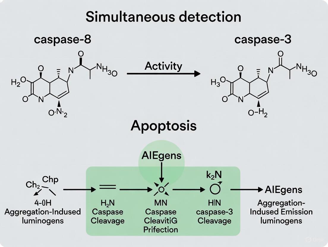
Direct monitoring of multiple enzyme activities in a single biological process is a powerful approach for disease diagnosis and therapeutic evaluation [3]. Apoptosis, or programmed cell death, is a fundamental biological process regulated by a cascade of caspases, which are protease enzymes. In this cascade, initiator caspases (e.g., caspase-8) activate executioner caspases (e.g., caspase-3), leading to the systematic dismantling of the cell [16]. Simultaneous detection of initiator and executioner caspase activities provides a dynamic view of the apoptotic process, offering valuable insights for screening anticancer drugs and studying cell death mechanisms [3]. Traditional multi-probe strategies face challenges like differential cellular uptake and distinct localization patterns. A single fluorescent probe capable of monitoring multiple caspase activities with a single-wavelength excitation minimizes this complexity and provides more accurate spatiotemporal information [3]. This application note deconstructs a novel probe based on Aggregation-Induced Emission Luminogens (AIEgens) designed for the sequential, real-time monitoring of caspase-8 and caspase-3 activities in living cells.
Probe Design and Working Mechanism
Architectural Components
The probe (denoted as Probe 1) is a sophisticated molecular construct engineered for sequential activation by the caspase cascade. Its architecture consists of three key components [3]:
- Red-Emitting AIEgen: A maleimide-functionalized TPETH (TPETH-Mal) moiety, which emits red fluorescence (emission maximum ~650 nm) upon aggregation and is excitable at 405 nm.
- Green-Emitting AIEgen: An azide-functionalized tetraphenylsilole (TPS-N3) moiety, which emits green fluorescence (emission maximum ~480 nm) upon aggregation and is also excitable at 405 nm.
- Peptide Substrate Linker: A hydrophilic peptide sequence (DVEDIETD) serving as the specific substrate for caspases. This sequence contains the cleavage motifs for both caspase-3 (DVED) and caspase-8 (IETD), arranged to allow sequential cleavage.
Fundamental AIE Principle
The probe's operation hinges on the Aggregation-Induced Emission (AIE) phenomenon. Unlike traditional fluorophores that suffer from aggregation-caused quenching (ACQ), AIEgens are non-emissive in their molecularly dissolved state but become highly fluorescent upon aggregation [17]. This occurs because aggregation restricts intramolecular motions (RIM), prohibiting energy dissipation via non-radiative pathways and enabling strong fluorescence emission [3]. This property allows for the design of "turn-on" probes without the need for external quenchers.
Signaling Cascade and Sequential Activation
The probe is initially non-fluorescent in aqueous media like the cell cytoplasm. During apoptosis, it undergoes a sequential, two-step activation process that mirrors the enzymatic cascade [3].
Figure 1: The Caspase Cascade Activation and Sequential Fluorescence Turn-On Mechanism
As illustrated in Figure 1, the process begins when the initiator caspase-8 cleaves the IETD site on the probe. This cleavage releases the green-emitting TPS moiety, which, being hydrophobic, aggregates within the cellular environment. These aggregates exhibit intense green fluorescence due to the AIE effect, providing the first optical signal indicating caspase-8 activation [3]. Subsequently, the executioner caspase-3 cleaves the remaining DVED site. This second cleavage releases the red-emitting TPETH moiety, which also aggregates and lights up with red fluorescence, confirming the activation of the downstream executioner caspase and the commitment to apoptosis [3]. This sequential turn-on allows real-time monitoring of the entire caspase cascade activation from initiation to execution.
Quantitative Performance Data
The performance of Probe 1 was rigorously characterized in vitro and in live cells. Key quantitative data are summarized in the tables below.
Table 1: Photophysical Properties of AIEgens in Probe 1
| AIEgen Component | Absorption Maximum (nm) | Emission Maximum (nm) | Stokes Shift | Fluorescence Enhancement (Aggregated vs. Molecular) |
|---|---|---|---|---|
| TPS-N3 (Green) | 360 nm | 480 nm | 120 nm | 110-fold increase at 99% water fraction [3] |
| TPETH-Mal (Red) | Shoulder at 430 nm | 650 nm | >200 nm | Significant intensification with increased water fraction [3] |
Table 2: Enzymatic Performance and Specificity of Probe 1
| Parameter | Caspase-8 Response (Green Channel) | Caspase-3 Response (Red Channel) |
|---|---|---|
| Michaelis Constant (K_M) | 5.40 µM [3] | Data not provided in source |
| Catalytic Constant (k_cat) | 1.39 s⁻¹ [3] | Data not provided in source |
| Selectivity | High specificity for caspase-8; signal inhibited by Z-IETD-FMK [3] | High specificity for caspase-3; signal inhibited by Z-DEVD-FMK [3] |
| Signal Kinetics | Fluorescence intensified and saturated after 60 min incubation [3] | Fluorescence steadily intensified with incubation time [3] |
The data in Table 1 highlight the excellent optical properties of the AIEgens, including their large Stokes shifts, which minimize background interference. Table 2 confirms the probe's functionality as a specific substrate for its target enzymes, with kinetic parameters comparable to those found in previous literature [3].
Detailed Experimental Protocols
Protocol 1: In Vitro Validation of Probe 1 with Purified Caspases
This protocol outlines the steps to validate the specificity and enzymatic kinetics of Probe 1 using purified caspase enzymes.
Materials:
- Probe 1 (lyophilized powder)
- Active recombinant caspase-8 and caspase-3
- Caspase-8 inhibitor (Z-IETD-FMK) and caspase-3 inhibitor (Z-DEVD-FMK)
- Assay buffer (e.g., PBS or recommended caspase buffer)
- Dimethyl sulfoxide (DMSO)
- Fluorimeter or plate reader capable of 405 nm excitation and measuring emission at 480 nm and 650 nm
Procedure:
- Probe Solution Preparation: Dissolve the lyophilized Probe 1 in anhydrous DMSO to prepare a 1 mM stock solution.
- Sample Preparation: In assay buffer, dilute the Probe 1 stock to a final concentration of 5-10 µM.
- Inhibition Control Setup: Pre-incubate separate aliquots of the enzyme solution (caspase-8 or caspase-3) with their respective inhibitors (e.g., 10-30 µM) for 30 minutes at room temperature before adding the probe.
- Reaction Initiation: Add the target caspase (e.g., 1-10 U/mL) to the probe solution. For controls, add inhibitor-treated enzyme or buffer alone.
- Fluorescence Measurement: Immediately transfer the reaction mixture to a cuvette or multi-well plate.
- Place the sample in a fluorometer pre-heated to 37°C.
- Set excitation to 405 nm.
- Monitor the green fluorescence (480 nm) for caspase-8 assays and the red fluorescence (650 nm) for caspase-3 assays over 60-120 minutes.
- Data Analysis: Plot fluorescence intensity versus time. The signal from the caspase-treated sample should show a significant increase compared to the inhibitor-treated and enzyme-free controls, confirming specific cleavage.
Protocol 2: Real-Time Imaging of Apoptosis in Live HeLa Cells
This protocol describes the application of Probe 1 for visualizing caspase cascade activation in living cells induced to undergo apoptosis.
Materials:
- HeLa cells (or other relevant cell line)
- Probe 1 (DMSO stock)
- Apoptosis inducer: 0.5-1.0 mM Hydrogen Peroxide (H₂O₂) or 0.5 µM Staurosporine
- Cell culture medium and reagents
- Confocal microscope or live-cell imaging system with a 405 nm laser and filters for FITC/green and Texas Red/red channels
Procedure:
- Cell Culture: Seed HeLa cells into a glass-bottom dish or imaging plate at a suitable density (e.g., 50-70% confluency) and allow them to adhere overnight in a 37°C, 5% CO₂ incubator.
- Probe Loading: Replace the culture medium with fresh medium containing 5-10 µM Probe 1. Incubate the cells for 30-60 minutes under growth conditions.
- Induction of Apoptosis: After probe loading, add the apoptosis inducer (e.g., H₂O₂) directly to the medium. For a negative control, replace the medium with fresh medium without the inducer.
- Real-Time Imaging:
- Place the cell culture dish on the microscope stage maintained at 37°C and 5% CO₂.
- Using a 405 nm excitation laser, acquire simultaneous or sequential images of the green and red channels every 5-10 minutes over several hours (e.g., 4-7 hours).
- Focus on capturing the sequential turn-on: the appearance of green fluorescence in the cytoplasm (indicating caspase-8 activation) followed by the emergence of red fluorescence (indicating caspase-3 activation).
- Image Analysis: Use image analysis software to quantify the mean fluorescence intensity in each channel over time. The kinetic data will visually demonstrate the cascade from initiator to executioner caspase.
Figure 2: Experimental Workflow for Probe Validation and Application
The Scientist's Toolkit: Essential Research Reagents
The following table catalogs key reagents and materials essential for experiments involving caspase activity detection and AIE-based probes.
Table 3: Research Reagent Solutions for Caspase and AIEgen Studies
| Reagent/Material | Function/Description | Example Product / Citation |
|---|---|---|
| AIEgen-based Caspase Probe | Single probe for sequential detection of caspase-8 and -3; single-wavelength excitable. | Probe 1 (TPETH–DVEDIETD–TPS) [3] |
| Fluorogenic Caspase Substrates | Conventional substrates for measuring activity of specific caspases via fluorimeter. | Ac-DEVD-AMC (for caspase-3/7) [18]; IETD-based substrates (for caspase-8) [19] |
| Caspase Inhibitors | Peptide-based inhibitors to confirm caspase-specific signal in assays. | Z-IETD-FMK (caspase-8 inhibitor); Z-DEVD-FMK (caspase-3/7 inhibitor) [3] |
| Luminescent Caspase Assay | Homogeneous, "add-mix-measure" format for high-throughput screening of caspase-3/7 activity. | Caspase-Glo 3/7 Assay [20] |
| Live-Cell Caspase Detection Dyes | Cell-permeant reagents for no-wash, real-time detection of caspase-3/7 activity. | CellEvent Caspase-3/7 Green/Red [16] |
| Genetic Caspase Reporters | Stable biosensors for long-term, real-time imaging of caspase dynamics in 2D/3D models. | ZipGFP-based caspase-3/7 reporter [5] |
| Apoptosis Inducers | Chemical agents used to trigger the apoptotic pathway in experimental models. | Hydrogen Peroxide (H₂O₂), Staurosporine, Camptothecin [3] [16] |
The deconstruction of Probe 1 reveals a rationally designed biosensing platform that effectively leverages the unique properties of AIEgens. Its core innovation lies in the integration of two distinctive AIEgens with a caspase-specific peptide substrate into a single molecular entity, enabling the sequential, real-time monitoring of the caspase cascade activation. This design overcomes key limitations of traditional multi-probe strategies. The detailed protocols and performance data provided here equip researchers with the necessary information to implement this technology for advanced apoptosis studies, particularly in the context of anticancer drug evaluation and the dissection of complex cell death pathways.
Apoptosis, or programmed cell death, is a fundamental biological process essential for development and maintaining cellular homeostasis in multicellular organisms. This genetically programmed, ATP-dependent mechanism eliminates unnecessary or potentially harmful cells [21]. A central feature of apoptosis is the activation of a cascade of cysteine-aspartic proteases, known as caspases, which function as crucial mediators at different stages of the cell death pathway [3] [21]. In a typical apoptosis process, initiator caspases (e.g., caspase-8 or -9) activate effector caspases (e.g., caspase-3), which ultimately execute cell death [3]. Caspase-3 serves as a key downstream effector that cleaves numerous cellular substrates, making its activation a point of no return in the apoptotic pathway [22]. The ability to monitor this caspase cascade activation, particularly the sequential activities of caspase-8 and caspase-3, provides valuable insights for evaluating the efficacy of anticancer therapies and understanding fundamental biological processes [3] [22].
The development of fluorescent probes that can monitor multiple enzyme activities in a single biological process represents a significant advancement for disease diagnosis and therapeutic monitoring [3]. Traditional approaches using multiple fluorescent probes with different emission colors face challenges including different biological locations, varied cellular uptake abilities, and the need for distinctive fluorophore/quencher pairs [3]. Furthermore, real-time multicolor monitoring of multiple enzymes with single-wavelength excitation minimizes complexity in fluorescence imaging, but traditional fluorescent dyes with different emission colors typically have different absorption wavelengths [3]. Recent innovations in fluorogens with aggregation-induced emission characteristics (AIEgens) have provided new opportunities to overcome these limitations and develop sophisticated probes for monitoring caspase activities in living cells [3].
Biological Foundation: Caspase Signaling Pathways
The Extrinsic Pathway and Caspase-8 Initiation
The extrinsic apoptosis pathway is triggered when cells receive death signals from their environment through specific cell surface receptors. This receptor-linked pathway involves ligands binding to death receptors on the cell surface, ultimately activating caspase-8 as a key regulatory initiator caspase [21]. Important components include TNF-α (tumor necrosis factor-alpha), a cytokine produced by macrophages that serves as a major extrinsic mediator of apoptosis by binding to TNFR1 and activating caspases, and Fas, a surface receptor generated by T-cells that increases production during infection [21]. When Fas binds to its ligand, apoptosis is triggered through caspase activation [21]. As an initiator caspase, caspase-8 exists as an inactive procaspase monomer that can self-activate with the participation of other proteins and subsequently activate downstream effector caspases [22].
The Intrinsic Pathway and Mitochondrial Involvement
The intrinsic apoptosis pathway activates when cells experience internal stress from factors including DNA damage (from x-ray or UV light exposure, chemotherapeutic agents), hypoxia, or accumulation of misfolded proteins [21]. This pathway involves mitochondrial inner membrane depolarization and cytochrome c release from the intermembrane space into the cytosol [8]. Cytochrome c then binds with APAF-1, forming a complex known as the apoptosome that activates caspase-9 [21]. The Bcl-2 protein family tightly regulates the intrinsic pathway through a balance of pro-apoptotic and anti-apoptotic members [21]. Anti-apoptotic proteins including Bcl-2 block cell death, while pro-apoptotic proteins detect death signals and trigger the process [21].
Caspase-3 as the Executioner
Caspase-3 serves as the primary downstream effector caspase in both extrinsic and intrinsic pathways [22]. Initially inactive in cells, caspase-3 becomes activated through cleavage by upstream initiator caspases including caspase-8, -9, and -10 [22]. Once activated, caspase-3 catalyzes the cleavage of major cellular proteins and chromatin condensation, activates DNase enzymes causing DNA fragmentation, and ultimately leads to the formation of apoptotic bodies [21] [22]. Single-cell fluorescence resonance energy transfer (FRET) analysis has demonstrated that once initiated, caspase-3 activation occurs rapidly—within 5-15 minutes—suggesting an "all or nothing" fashion of apoptosis execution [23] [8]. This rapid activation is particularly dependent on caspase-3-mediated feedback loops when apoptosis onset is slow [23].
Caspase Cascade Interconnectivity
The apoptotic network features extensive crosstalk between pathways, creating a tightly regulated system emerging from high connectivity [24]. Boolean modeling of apoptosis has revealed the particular importance of feedback loops in regulating the complex interplay of pro- and anti-apoptotic factors [24]. For example, an unexpected feedback from Smac release to RIP could further increase complex II formation [24]. The interconnectivity ensures that caspase activation, particularly of caspase-3, represents a commitment to cellular demise, making it an excellent biomarker for monitoring apoptosis progression [23] [8].
Diagram 1: Caspase Signaling Pathways in Apoptosis. This diagram illustrates the intrinsic and extrinsic pathways of apoptosis activation, highlighting the central role of caspase-3 as the executioner protease and its activation by upstream initiator caspases (-8 and -9).
Molecular Design of AIEgen-Based Caspase Probes
Aggregation-Induced Emission (AIE) Mechanism
Aggregation-Induced Emission (AIE) represents a unique photophysical phenomenon that has revolutionized fluorescence-based biosensing. Unlike traditional fluorophores that suffer from aggregation-caused quenching (ACQ)—where fluorescence diminishes at high concentrations or in aggregate states—AIEgens exhibit weak or no emission in molecularly dissolved states but become highly fluorescent in aggregate forms [3]. The mechanism behind AIEgens has been clarified to result from the restriction of intramolecular motions (RIM), which prohibits energy dissipation via non-radiative channels and enables radiative decay [3]. This property allows for the design of fluorescence turn-on probes without incorporating quenchers, significantly simplifying probe architecture while improving signal-to-noise ratios [3]. Additionally, AIEgens typically display large Stokes shifts, making it possible to obtain fluorophores with different emission colors upon single-wavelength excitation—a crucial advantage for multiplexed imaging applications [3].
Probe Architecture and OFF-ON Switching Mechanism
The design of AIEgen-based caspase probes typically consists of three main components: two AIE fluorogens with distinctive emission colors (typically green and red) but excitable at a single wavelength, and a hydrophilic peptide substrate containing specific cleavage sequences for both caspase-8 and caspase-3 [3]. In the intact state, the probe remains non-fluorescent in aqueous media because the hydrophilic peptide keeps the AIEgens in a molecularly dissolved state, allowing free intramolecular motions that dissipate energy non-radiatively [3]. This constitutes the "OFF" state. During apoptosis, initiator caspase-8 first cleaves its specific recognition sequence (IETD) within the peptide substrate, liberating one AIEgen (typically green-emitting) to form aggregates, thereby switching on its fluorescence [3]. Subsequently, effector caspase-3 cleaves its recognition sequence (DEVD), releasing the second AIEgen (typically red-emitting) to aggregate and fluoresce [3]. This sequential cleavage and fluorescence activation enables real-time monitoring of the caspase cascade in living cells.
Advantages Over FRET-Based Probes
AIEgen-based caspase probes offer several significant advantages compared to traditional FRET-based caspase substrates. While FRET probes rely on the physical separation of fluorophore-quencher pairs or two fluorophores with overlapping spectra, AIEgen probes operate through a fundamentally different mechanism that doesn't require complex quenching systems [3] [25]. FRET efficiency in traditional caspase substrates diminishes when cleavage separates the donor and acceptor fluorophores, but these probes often suffer from high background signals and limited signal-to-noise ratios [25]. In contrast, AIEgen probes provide extremely low background fluorescence in their intact state and significant fluorescence enhancement upon caspase-mediated cleavage and subsequent aggregation [3]. This "light-up" characteristic, combined with the large Stokes shifts and resistance to photobleaching, makes AIEgen probes particularly suitable for long-term, real-time monitoring of apoptosis in live cells and for evaluating therapeutic efficiency of anticancer drugs [3] [22].
Diagram 2: AIEgen Probe OFF-ON Activation Mechanism. This diagram illustrates the sequential activation process where caspase-8 cleavage first liberates the green-emitting AIEgen, followed by caspase-3 cleavage releasing the red-emitting AIEgen, with both becoming fluorescent upon aggregation.
Experimental Validation and Quantitative Analysis
Probe Synthesis and Characterization
The synthesis of dual-caspase AIEgen probes involves several well-defined steps as described in the research by Yuan et al. [3]. The process begins with the synthesis of azide-functionalized tetraphenylsilole (TPS-N3), which serves as the green-emitting AIEgen (λem = 480 nm), and malimide-functionalized TPETH (TPETH-Mal), which serves as the red-emitting AIEgen (λem = 650 nm) [3]. Both AIEgens demonstrate characteristic aggregation-induced emission properties, with TPS-N3 showing a 110-fold fluorescence enhancement at 99% water fraction compared to DMSO solution [3]. The hydrophilic peptide substrate (DVEDIETD) containing cleavage sites for both caspase-8 (IETD) and caspase-3 (DVED) is then prepared. The "click" reaction between TPS-N3 and the peptide sequence CDVEDIETDPra yields CDVEDIETD-TPS with a terminal thiol group, which is subsequently reacted with TPETH-Mal to produce the final probe, designated as Probe 1 [3]. After HPLC purification and freeze-drying, the probe is obtained as a red powder with 46% yield [3]. Similar synthetic strategies can be applied to create probes targeting different caspase combinations, such as Probe 2 (TPETH-DVEDLEHD-TPS) for caspase-9 and caspase-3 detection [3].
In Vitro Caspase Activity Assessment
The functionality of AIEgen caspase probes is first validated through in vitro studies with recombinant caspases. When Probe 1 is incubated with caspase-8, the green fluorescence (from TPS residue) steadily intensifies, reaching saturation after approximately 60 minutes of incubation [3]. This fluorescence enhancement results from caspase-8-mediated cleavage of the peptide substrate and subsequent formation of TPS residue aggregates, as confirmed by laser light scattering (LLS) and transmission electron microscope (TEM) analyses [3]. The specificity of this reaction is verified through control experiments with caspase-8 inhibitor (Z-IETD-FMK), which effectively abolishes the fluorescence turn-on response [3]. Similarly, incubation of Probe 1 with caspase-3 induces a time-dependent increase in red fluorescence (from TPETH residue), which is prohibited when caspase-3 inhibitor (Z-DEVD-FMK) is present [3]. The selectivity of Probe 1 is further confirmed by challenging it with various caspases and other proteins, demonstrating significant fluorescence increase only with the corresponding target caspases [3].
Kinetic Analysis and Sensitivity Determination
Quantitative analysis of the caspase detection capability reveals excellent sensitivity and well-defined kinetic parameters for the AIEgen probes. As shown in Table 1, the PL intensity at 480 nm after incubating Probe 1 with different concentrations of caspase-8 shows a linear relationship with caspase-8 concentration (R² = 0.97), enabling quantification of caspase-8 levels [3]. Kinetic analysis of the enzymatic reaction provides Michaelis constants (KM) and kinetic constants (kcat) that are comparable to those reported in previous studies [3]. For caspase-3 detection, single-cell analysis using FRET-based techniques has demonstrated that once initiated, caspase-3 activation is extremely rapid, completing within 5 minutes or less [8]. This rapid activation occurs almost simultaneously with mitochondrial membrane depolarization and just prior to characteristic morphological changes associated with apoptosis [8].
Table 1: Quantitative Parameters for AIEgen Caspase Probes
| Parameter | Caspase-8 Detection | Caspase-3 Detection | Experimental Conditions |
|---|---|---|---|
| Linear Range | Concentration-dependent | N/R | Probe 1 with recombinant caspase-8 [3] |
| Detection Sensitivity | Linear fit R² = 0.97 | N/R | PL intensity at 480 nm [3] |
| Kinetic Parameters | KM = 5.40 μM, kcat = 1.39 s⁻¹ | N/R | Michaelis-Menten kinetics [3] |
| Activation Kinetics | N/R | ≤15 minutes (HeLa cells) [23] | Single-cell FRET analysis [23] |
| Activation Speed | N/R | ≤5 minutes (COS-7 cells) [8] | FRET with CFP-DEVD-YFP [8] |
| Mitochondrial Correlation | N/R | 76% simultaneous with depolarization [8] | TMREE staining [8] |
N/R: Not explicitly reported in the cited references
Cellular Validation and Apoptosis Monitoring
The practical application of AIEgen caspase probes is demonstrated in living cells undergoing apoptosis. In HeLa cells induced with hydrogen peroxide (H₂O₂), Probe 1 successfully monitors the caspase cascade activation through sequential fluorescence turn-on [3]. Initially non-fluorescent in aqueous media, the probe first activates green fluorescence when caspase-8 cleaves its recognition sequence during early apoptosis, followed by red fluorescence activation as caspase-3 cleaves its site [3]. This sequential activation allows real-time tracking of apoptosis progression and has been further explored for evaluating the therapeutic efficiency of anticancer drugs [3]. The ability to monitor both initiator and effector caspase activities with a single probe in living cells provides significant advantages over traditional methods such as TUNEL assay, Annexin V staining, or Western blot analysis, which typically provide endpoint measurements rather than real-time kinetic data [21] [26]. Importantly, the probe design strategy has proven generalizable, opening new avenues for real-time, multiplexed imaging of cellular enzyme activities in various biological processes [3].
Research Reagent Solutions
Table 2: Essential Research Reagents for Caspase Detection Assays
| Reagent / Assay | Function / Application | Key Features |
|---|---|---|
| AIEgen Caspase Probes (e.g., Probe 1: TPETH-DVEDIETD-TPS) | Simultaneous detection of caspase-8 and caspase-3 activities in live cells [3] | Dual emission (green/red), single-wavelength excitation, sequential activation, low background [3] |
| FRET-Based Caspase Substrates (e.g., CFP-DEVD-YFP) | Monitoring caspase-3 activation kinetics in single cells [23] [8] [25] | Ratio-metric measurement, suitable for real-time kinetics, shows rapid activation (<15 min) [23] [8] |
| Annexin V Binding Assays | Detection of phosphatidylserine externalization on cell membrane [26] | Early apoptosis marker, can distinguish apoptosis from necrosis with DNA stains [26] |
| Luminescent Annexin V Assays (e.g., RealTime-Glo) | Real-time monitoring of apoptosis and necrosis without washing steps [26] | Homogeneous "no-wash" format, suitable for high-throughput screening [26] |
| Caspase Inhibitors (e.g., Z-IETD-FMK, Z-DEVD-FMK) | Specific inhibition of caspase-8 and caspase-3, respectively [3] | Validates specificity of caspase probes, mechanistic studies [3] |
| Mitochondrial Membrane Potential Dyes (e.g., TMREE, JC-1) | Detection of mitochondrial membrane depolarization during apoptosis [8] | Correlates caspase activation with mitochondrial events [8] |
| DNA Staining Dyes (e.g., Propidium Iodide, 7-AAD) | Distinguishing apoptotic from necrotic cells [26] | Membrane impermeant, labels dead cells, used with Annexin V [26] |
Detailed Experimental Protocols
Protocol 1: AIEgen Probe Preparation and Cellular Application
Materials Required:
- AIEgen caspase probe (e.g., Probe 1: TPETH-DVEDIETD-TPS)
- Anhydrous DMSO for stock solution preparation
- Appropriate cell culture medium (serum-free recommended for incubation)
- Apoptosis inducer (e.g., hydrogen peroxide, staurosporine, TNF-α)
- Caspase inhibitors for control experiments (Z-IETD-FMK for caspase-8, Z-DEVD-FMK for caspase-3)
- Confocal microscope or fluorescence microplate reader with appropriate filter sets
Procedure:
- Probe Stock Solution Preparation: Prepare a 1-5 mM stock solution of the AIEgen caspase probe in anhydrous DMSO. Aliquot and store at -20°C protected from light.
- Working Solution Preparation: Dilute the stock solution in serum-free cell culture medium to achieve a final working concentration of 5-20 μM. Gently vortex to ensure complete mixing.
- Cell Preparation: Plate cells in appropriate imaging vessels (e.g., glass-bottom dishes, multi-well plates) and culture until 60-80% confluent.
- Probe Loading: Remove culture medium and replace with the probe working solution. Incubate for 30-60 minutes under standard culture conditions (37°C, 5% CO₂).
- Apoptosis Induction: After probe loading, apply apoptosis inducer at predetermined concentrations. For H₂O₂-induced apoptosis in HeLa cells, 100-500 μM is typically effective [3].
- Control Samples: Include control samples with caspase inhibitors: pre-treat cells with 20-50 μM Z-IETD-FMK (caspase-8 inhibitor) or Z-DEVD-FMK (caspase-3 inhibitor) for 1-2 hours before apoptosis induction.
- Real-Time Imaging: Transfer samples to a pre-warmed microscope stage or microplate reader. Acquire images/readings every 5-15 minutes for 2-8 hours using appropriate excitation/emission filters (e.g., 405 nm excitation, 480/650 nm emission).
- Data Analysis: Quantify fluorescence intensities in green and red channels. Calculate kinetic parameters and determine the sequence of caspase activation.
Protocol 2: Validation Using FRET-Based Caspase-3 Substrate
Materials Required:
- FRET caspase substrate (e.g., CFP-DEVD-YFP plasmid)
- Transfection reagent
- Apoptosis inducers (staurosporine, etoposide, TNF-α)
- Confocal microscope with FRET capability
- Carbonyl cyanide m-chlorophenyl hydrazone (CCCP, positive control)
Procedure:
- Cell Transfection: Transfect cells with CFP-DEVD-YFP construct using standard transfection protocols. Incubate for 24-48 hours to allow expression.
- Apoptosis Induction: Apply apoptosis inducer at optimized concentrations (e.g., 1 μM staurosporine for COS-7 cells) [8].
- Real-Time FRET Imaging: Acquire time-lapse images using 405 nm excitation, with emission collection at 475 nm (CFP) and 525 nm (YFP). Calculate FRET ratio (YFP/CFP emission).
- Mitochondrial Membrane Potential Monitoring: Co-stain with TMREE (tetramethylrhodamine ethyl ester) to simultaneously monitor mitochondrial depolarization [8].
- Kinetic Analysis: Determine the timing and rapidity of caspase-3 activation. Note that completion typically occurs within 5-15 minutes once initiated [23] [8].
Data Interpretation Guidelines
- Sequential Activation: In AIEgen probes, green fluorescence (caspase-8) typically precedes red fluorescence (caspase-3) during normal apoptosis progression [3].
- Rapid Kinetics: Caspase-3 activation occurs rapidly (≤15 minutes) once initiated, following variable lag times depending on inducer and concentration [23].
- Single-Cell Heterogeneity: Apoptosis initiation timing varies among individual cells, but execution is consistently rapid once commitment occurs [23] [8].
- Mitochondrial Correlation: Caspase-3 activation typically coincides with (76% of cells) or slightly follows (∼5 minutes) mitochondrial membrane depolarization [8].
- Inhibition Controls: Specific caspase inhibitors should block corresponding fluorescence activation, confirming probe specificity [3].
Diagram 3: Experimental Workflow for Caspase Cascade Monitoring. This diagram outlines the key steps in applying AIEgen probes for monitoring sequential caspase activation, from cell preparation and probe loading to real-time imaging and data validation.
The development of AIEgen-based fluorescent probes with OFF-ON activation through sequential caspase cleavage represents a significant advancement in apoptosis research and therapeutic monitoring. These probes leverage the unique photophysical properties of AIEgens—particularly their low background in molecularly dissolved states and strong emission upon aggregation—to create highly sensitive sensors for caspase activities [3]. The sequential activation mechanism, where caspase-8 cleavage first liberates a green-emitting AIEgen followed by caspase-3 cleavage releasing a red-emitting AIEgen, enables real-time tracking of apoptosis progression in living cells [3]. This capability provides researchers and drug development professionals with a powerful tool for evaluating the efficacy of anticancer therapies and understanding the fundamental biology of programmed cell death.
The quantitative data obtained from these probes reveals crucial kinetic parameters of apoptosis, including the remarkably rapid nature of caspase-3 activation (≤15 minutes) once initiated [23] [8]. The correlation between caspase activation and mitochondrial events, combined with the subsequent morphological changes characteristic of apoptosis, provides a comprehensive view of the cell death process [8]. Furthermore, the generalizable design strategy for these probes opens possibilities for multiplexed imaging of various enzymatic activities in biological processes beyond apoptosis [3]. As research continues, further refinement of these probes—including improved brightness, additional color options, and enhanced cellular targeting—will expand their applications in basic research, drug discovery, and potentially clinical diagnostics.
This application note provides a detailed protocol for the simultaneous detection of initiator caspase-8 and effector caspase-3 activity in living cells using a novel aggregation-induced emissiongen (AIEgen)-based fluorescent probe. The probe design leverages the unique photophysical properties of AIEgens to enable real-time, multiplexed imaging of the caspase cascade activation during apoptosis, a process crucial for evaluating the therapeutic efficiency of anticancer drugs [3] [27]. The following sections describe the probe design, a step-by-step protocol for its application from live-cell imaging to data acquisition, and methods for data analysis.
Probe Design and Working Principle
The probe, denoted as Probe 1 (TPETH–DVEDIETD–TPS), is a single molecular construct consisting of three key parts [3]:
- Two AIE fluorogens: A green-emitting tetraphenylsilole derivative (TPS) and a red-emitting tetraphenylethylene derivative (TPETH). Both fluorogens are excitable at a single wavelength (405 nm) but emit at distinct wavelengths (480 nm and 650 nm, respectively) [3].
- A hydrophilic peptide substrate: The sequence DVEDIETD serves as a specific cleavage site for caspases. The DVED motif is a substrate for the effector caspase-3, and the IETD motif is a substrate for the initiator caspase-8 [3].
Working Principle: In aqueous media, the probe is non-fluorescent due to the molecularly dissolved state of the AIEgens. During apoptosis, the sequential activation of caspase-8 and caspase-3 leads to the cleavage of the peptide substrate. This cleavage releases the hydrophobic AIEgen residues, which then aggregate due to their insolubility in water. The aggregation restricts intramolecular motion, thereby turning on fluorescence sequentially: green fluorescence (from TPS aggregates) upon caspase-8 cleavage, followed by red fluorescence (from TPETH aggregates) upon caspase-3 cleavage [3]. This dual signal turn-on allows for real-time monitoring of the caspase cascade.
Materials
Research Reagent Solutions
The following table lists the key reagents and materials required for the experiment.
Table 1: Essential Research Reagents and Materials
| Item Name | Function/Description |
|---|---|
| AIEgen Probe 1 (TPETH–DVEDIETD–TPS) | The core fluorescent probe for simultaneous detection of caspase-8 and caspase-3 activities [3]. |
| Cell Culture Medium (e.g., DMEM) | For maintaining and growing HeLa cells or other relevant cell lines. |
| Apoptosis Inducer (e.g., Hydrogen Peroxide, H₂O₂) | To initiate the apoptotic process in cells [3]. |
| Caspase Inhibitors (Z-IETD-FMK for caspase-8, Z-DEVD-FMK for caspase-3) | Specific inhibitors used as negative controls to confirm the selectivity of the probe [3]. |
| Dimethyl Sulfoxide (DMSO) | Solvent for preparing stock solutions of the probe and inhibitors. |
| Phosphate Buffered Saline (PBS) | For washing cells and diluting reagents. |
| Fixative Solution (e.g., 2–5% Formaldehyde) | For fixing cells after imaging, if required for endpoint analysis [28]. |
Experimental Protocol
Sample Preparation and Staining
- Cell Culture and Seeding: Culture HeLa cells (or your cell line of interest) in an appropriate medium. Seed the cells into a multi-well plate or glass-bottom dish suitable for live-cell imaging at a desired confluency (e.g., 60-70%) and allow them to adhere overnight.
- Probe Loading: Prepare a working solution of Probe 1 in serum-free culture medium or PBS. The optimal concentration must be determined empirically; a starting point is 10 µM. Remove the growth medium from the cells, add the probe solution, and incubate for a predetermined time (e.g., 30-60 minutes) at 37°C in the dark.
- Induction of Apoptosis: After probe loading, wash the cells gently with PBS to remove excess probe. Induce apoptosis by treating the cells with a known apoptogen, such as hydrogen peroxide (H₂O₂). For example, treat HeLa cells with 200 µM H₂O₂ [3]. Include control wells without the apoptogen to establish a baseline.
- Inhibitor Controls (Optional but Recommended): To confirm the specificity of the signal, pre-treat a separate set of cells with caspase-specific inhibitors (e.g., 20 µM Z-IETD-FMK for caspase-8 or Z-DEVD-FMK for caspase-3) for 1 hour before the addition of the probe and apoptogen [3].
Data Acquisition: Live-Cell Fluorescence Imaging
- Microscope Setup: Place the prepared sample on the stage of a confocal or widefield fluorescence microscope equipped with environmental control (37°C and 5% CO₂).
- Optical Configuration:
- Excitation: Use a 405 nm laser or LED light source.
- Emission Detection: Set up two separate channels to collect signals simultaneously:
- Green Channel: Collect emission at around 480 ± 20 nm for the TPS (caspase-8) signal.
- Red Channel: Collect emission at around 650 ± 20 nm for the TPETH (caspase-3) signal [3].
- Time-Lapse Imaging: Begin time-lapse acquisition immediately after adding the apoptogen. Set an appropriate interval (e.g., every 5-10 minutes) for image capture over a period of several hours (e.g., 4-6 hours) to monitor the kinetics of caspase activation.
- Image Acquisition Settings: Use low laser power and short exposure times to minimize phototoxicity and photobleaching. Ensure that the gain settings are within a linear range and avoid pixel saturation.
Alternative High-Throughput Data Acquisition: Imaging Flow Cytometry
For higher throughput and statistical power, imaging flow cytometry can be used as a complementary or alternative method.
- Sample Preparation: Prepare cells as described in Section 4.1. After the treatment with the probe and apoptogen, harvest the cells by gentle trypsinization or scraping at desired time points.
- Instrument Setup: Use an imaging flow cytometer (e.g., ImageStreamX from Luminex). Configure the instrument with a 405 nm laser for excitation and set up filters to detect emission in the green (e.g., 480/30 nm) and red (e.g., 650/30 nm) channels [28].
- Data Acquisition: Acquire images for at least 10,000 cells per sample to ensure robust statistics. The system will capture brightfield, darkfield (side scatter), and fluorescence images for each cell [28].
- Concentration Consideration: Concentrate the cell sample to approximately 20–30 million cells per mL in a volume of 50 µL to ensure efficient data acquisition [28].
Data Analysis and Interpretation
Quantitative Image Analysis
- Feature Extraction: From the acquired images (either from microscopy or imaging flow cytometry), extract quantitative features. For imaging flow cytometry data, this typically includes intensity-based features (e.g., mean fluorescence intensity in each channel) and morphological features (e.g., cell area, texture, and granularity) [28].
- Signal Quantification: Measure the fluorescence intensity in the green and red channels over time. The sequential turn-on of green signal (caspase-8) followed by red signal (caspase-3) indicates successful caspase cascade activation [3].
- Gating and Classification: Use software (e.g., IDEAS for ImageStream data) to gate on focused, single cells. Subsequently, create scatter plots of green vs. red fluorescence intensity to identify and quantify subpopulations of cells at different stages of apoptosis (e.g., caspase-8 active, caspase-3 active, or both) [28]. Advanced machine learning classifiers can also be trained on the image features for automated cell classification [28].
Key Quantitative Parameters
The following table summarizes the key quantitative data and optical properties associated with Probe 1.
Table 2: Key Quantitative Data for Probe 1 and its Components [3]
| Parameter | Value / Description | Significance |
|---|---|---|
| TPS Emission Maximum | 480 nm (Green) | Indicates caspase-8 activity upon cleavage. |
| TPETH Emission Maximum | 650 nm (Red) | Indicates caspase-3 activity upon cleavage. |
| Shared Excitation Wavelength | 405 nm | Simplifies imaging by allowing single-wavelength excitation for both signals. |
| Fluorescence Enhancement (upon aggregation) | >110-fold for TPS | Confirms the AIE property and the "light-up" response upon caspase cleavage. |
| Michaelis Constant (Kₘ) for Caspase-8 | 5.40 µM | Provides a measure of the enzyme-substrate affinity. |
| Kinetic Constant (k_cat) for Caspase-8 | 1.39 s⁻¹ | Provides a measure of the catalytic rate. |
Schematic Workflow and Signaling Pathway
The following diagram illustrates the experimental workflow and the probe's mechanism of action.
Troubleshooting
- Weak or No Fluorescence Signal: Confirm apoptosis induction is working correctly. Titrate the probe concentration and ensure incubation time is sufficient. Verify microscope settings and filter configurations.
- High Background Fluorescence: Increase the number of washes after probe loading to remove unbound probe. Ensure the use of serum-free medium during probe loading to prevent nonspecific adsorption.
- Non-Sequential Signal Activation: Optimize the concentration of the apoptosis inducer. Confirm the specificity of the signal using caspase inhibitors.
- Poor Cell Viability during Imaging: Minimize phototoxicity by reducing laser power and increasing acquisition intervals. Ensure the environmental chamber maintains optimal temperature and CO₂ levels.
The activation of caspase enzymes is a critical event in the execution phase of apoptosis, a fundamental process of programmed cell death essential for eliminating cancerous cells [29]. Most signaling pathways activated by anticancer drugs ultimately converge on the activation of caspases, which act as common death effector molecules in various forms of cell death [29]. These cysteine proteases are synthesized as inactive zymogens and become activated through proteolytic cleavage, forming a proteolytic cascade with positive feedback properties [29]. Caspases are categorized into initiator caspases (including caspase-8) that transduce various signals into protease activity, and effector caspases (including caspase-3) that cleave various cytoplasmic and nuclear substrates, leading to the morphological hallmarks of apoptosis [29].
The significance of caspase activation extends beyond basic biology to therapeutic applications. Failure to activate apoptotic pathways in response to drug treatment may lead to tumor resistance, making the factors affecting caspase activation important determinants of drug sensitivity [29]. The ability to simultaneously monitor multiple caspase activities in a given biological process provides an effective approach for evaluating the therapeutic efficiency of anticancer drugs during early-stage apoptosis [3] [27]. This protocol details the application of a novel aggregation-induced emissiongen (AIEgen)-based probe for real-time, multiplexed imaging of caspase-8 and caspase-3 activation in living cells, enabling rapid assessment of drug efficacy in preclinical models.
Principle of Simultaneous Caspase-8 and Caspase-3 Detection Using AIEgens
AIEgen Probe Design and Mechanism
The AIEgen-based detection system utilizes a single fluorescent probe engineered to target two caspase activities simultaneously in living cells [3] [27]. This probe consists of three fundamental components:
- Two AIE fluorogens with distinctive green and red emission colors excitable at a single wavelength
- A hydrophilic peptide substrate (DVEDIETD) containing recognition sequences for caspase-8 (IETD) and caspase-3 (DVED)
- Linker chemistry connecting the components into a unified molecular probe [3]
The operational mechanism relies on the unique aggregation-induced emission characteristics of the AIEgens. In aqueous media, the probe remains non-fluorescent due to the molecularly dissolved state of the AIEgens. Upon specific cleavage by activated caspases during apoptosis, the hydrophobic AIEgens are released and subsequently form aggregates, restricting their intramolecular motions and activating fluorescence emission [3]. The design enables sequential activation: caspase-8 cleavage first releases the green-emitting AIEgen, followed by caspase-3 cleavage releasing the red-emitting AIEgen, providing temporal resolution of the caspase cascade activation [3].
Caspase Signaling Pathways in Anticancer Drug Response
Caspase activation can be initiated through different entry sites, primarily the death receptor pathway (extrinsic) and the mitochondrial pathway (intrinsic) [29]. The extrinsic pathway is triggered by death receptors of the tumor necrosis factor superfamily, leading to caspase-8 activation, while the intrinsic pathway involves mitochondrial release of cytochrome c, resulting in caspase-9 activation [29]. These pathways converge on the activation of executioner caspases, including caspase-3 and caspase-7 [29]. For many anticancer therapies, including cytotoxic drugs, γ-irradiation, and immunotherapy, the mitochondrial pathway serves as the primary activation route, though crosstalk exists between pathways through molecules like Bid, which interconnects caspase-8 activation with mitochondrial amplification [29].
Figure 1: Caspase Signaling Pathways in Anticancer Drug Response. This diagram illustrates the two principal apoptosis pathways activated by anticancer therapies and their convergence on effector caspase activation.
Materials and Reagents
Research Reagent Solutions
Table 1: Essential Research Reagents for AIEgen-Based Caspase Detection
| Reagent/Kit | Function/Application | Key Features |
|---|---|---|
| AIEgen Probe (TPETH-DVEDIETD-TPS) | Simultaneous detection of caspase-8 and caspase-3 activities | Contains dual AIE fluorogens with green/red emission; single-wavelength excitation (405 nm) [3] |
| CellEvent Caspase-3/7 Green Detection Reagent | Flow cytometric detection of activated caspase-3/7 | Fluorogenic substrate with DEVD peptide; emission 511/533 nm; compatible with SYTOX AADvanced dead cell stain [30] |
| Cisplatin | Apoptosis-inducing anticancer drug | DNA crosslinking agent; induces intrinsic apoptotic pathway; caspase-dependent cell death [31] |
| Z-IETD-FMK | Caspase-8 inhibitor | Specific inhibitor for caspase-8; used as negative control to confirm assay specificity [3] |
| Z-DEVD-FMK | Caspase-3 inhibitor | Specific inhibitor for caspase-3; used as negative control to confirm assay specificity [3] |
| Cell culture media (DMEM/RPMI-1640) | Cell maintenance and treatment | Standard culture media supplemented with fetal bovine serum and antibiotics [31] |
Equipment and Instrumentation
- Fluorescence microscope with capability for time-lapse imaging and appropriate filter sets for green (∼480 nm) and red (∼650 nm) emission detection
- Flow cytometer with 488 nm laser excitation and capability for multicolor detection
- Cell culture facility including CO₂ incubator, biological safety cabinet, and centrifuges
- Spectrofluorometer for in vitro characterization of fluorescence properties
- High-performance liquid chromatography system for probe purification and analysis
Protocol for Evaluating Anticancer Drug Efficiency
Cell Culture and Drug Treatment
- Cell Preparation: Culture appropriate cancer cell lines (e.g., HeLa, 4T1, or other relevant models) in DMEM or RPMI-1640 media supplemented with 10% fetal bovine serum and 1% penicillin/streptomycin/L-glutamine at 37°C in a 5% CO₂ atmosphere [3] [31].
- Seeding Density: Plate cells at a density of 200,000 cells/mL in appropriate culture vessels (multi-well plates, chambered coverslips) and grow for 24-48 hours to reach 70-80% confluency [31].
- Drug Treatment: Prepare fresh solutions of the anticancer drug of interest (e.g., cisplatin at clinically relevant concentrations, typically 1-100 µM depending on cell line sensitivity) in basal culture media [31].
- Experimental Groups: Include the following experimental conditions:
- Untreated control group (vehicle only)
- Drug-treated group
- Drug + caspase inhibitor control groups (pre-treated with 20 µM Z-VAD-FMK for 30 min or specific caspase inhibitors) [31]
- Treatment Duration: Incubate cells with drug treatments for predetermined time points (e.g., 2, 4, 6, 8, 12, 24 hours) to capture temporal caspase activation dynamics.
AIEgen Probe Application and Imaging
- Probe Preparation: Prepare fresh working solution of the AIEgen probe (TPETH-DVEDIETD-TPS) in DMSO or appropriate aqueous buffer according to manufacturer specifications [3].
- Probe Application: Add the AIEgen probe to drug-treated and control cells at optimal concentration (determined empirically, typically 1-10 µM) and incubate at 37°C for 30-60 minutes [3].
- Live-Cell Imaging: Perform real-time imaging using a fluorescence microscope with maintained physiological conditions (37°C, 5% CO₂). Use single-wavelength excitation (405 nm) with sequential capture of green (480 nm) and red (650 nm) emission channels [3].
- Time-Course Monitoring: Acquire images at regular intervals (e.g., every 10-30 minutes) for up to 6 hours to monitor sequential caspase activation dynamics.
- Image Analysis: Quantify fluorescence intensities in both channels using image analysis software, calculating fold-change increases relative to baseline and inhibitor controls.
Figure 2: Experimental Workflow for AIEgen-Based Caspase Detection. This diagram outlines the sequential steps from cell treatment to quantitative analysis of caspase activation.
Flow Cytometry Analysis (Alternative Method)
- Cell Harvesting: Gently detach adherent cells using non-enzymatic dissociation buffer to preserve cell surface integrity and caspase activities.
- Staining Procedure: Resuspend cells in complete media containing the AIEgen probe (1-10 µM) and incubate for 30-60 minutes at 37°C protected from light [30].
- Viability Staining: If desired, add viability stain (e.g., SYTOX AADvanced) to distinguish apoptotic cells from necrotic/late apoptotic populations [30].
- Flow Cytometry Acquisition: Analyze cells using a flow cytometer with 405 nm excitation, collecting green fluorescence (530/30 nm filter) and red fluorescence (670 nm LP filter).
- Data Analysis: Use flow cytometry software to quantify the percentage of cells positive for caspase-8 activation (green), caspase-3 activation (red), or both, comparing drug-treated versus control populations.
Data Analysis and Interpretation
- Signal Quantification: Calculate fluorescence intensity ratios (drug-treated/control) for both caspase-8 and caspase-3 signals at each time point.
- Temporal Analysis: Determine the sequence and kinetics of caspase activation. Typically, caspase-8 activation peaks within 40 minutes, followed by caspase-3 activation in drug-induced apoptosis [3].
- Dose-Response Assessment: Compare caspase activation levels across different drug concentrations to establish potency and efficacy parameters.
- Statistical Analysis: Perform appropriate statistical tests (e.g., ANOVA with post-hoc testing) to determine significance between treatment groups. Experimental replicates should include at least n=3 independent experiments.
Expected Results and Data Interpretation
Quantitative Caspase Activation Profiles
Table 2: Expected Caspase Activation Dynamics Following Cisplatin Treatment
| Time Post-Treatment | Caspase-8 Activation (Green Fluorescence) | Caspase-3 Activation (Red Fluorescence) | Interpretation |
|---|---|---|---|
| 0-30 minutes | Baseline (1.0-fold) | Baseline (1.0-fold) | Pre-activation phase |
| 30-60 minutes | 2.5-3.5-fold increase [3] | 1.0-1.5-fold increase | Early caspase-8 activation |
| 1-2 hours | Peak activation (3.3-3.7-fold) [7] | 2.0-3.0-fold increase | Caspase-8 peak; caspase-3 activation |
| 2-4 hours | Sustained elevation | Peak activation (>3.0-fold) | Full caspase cascade execution |
| 4-6 hours | Gradual decline | Sustained elevation | Apoptosis progression |
| 6+ hours | Variable depending on cell type | Variable depending on cell type | Late apoptosis/secondary necrosis |
Assessment of Drug Efficacy
The sequential activation pattern of caspase-8 followed by caspase-3 provides a dynamic profile of apoptotic commitment in response to anticancer drug treatment. Effective therapeutics should demonstrate:
- Dose-dependent increase in both caspase-8 and caspase-3 activation
- Appropriate temporal sequence with caspase-8 preceding caspase-3 activation
- Significant fold-increases compared to untreated controls (typically >2.5-fold for caspase-8 and >3.0-fold for caspase-3 in responsive models) [3]
- Inhibition of signal in caspase inhibitor pre-treated groups, confirming specificity
The ratio of caspase-8 to caspase-3 activation and their absolute signal intensities can serve as quantitative indicators of therapeutic efficiency, allowing comparison between different drug candidates or combination regimens.
Troubleshooting and Technical Considerations
Low Signal Intensity:
- Confirm probe concentration and incubation time optimization
- Verify drug activity and cell responsiveness
- Check instrument settings and filter configurations
Non-Sequential Activation:
- Validate caspase specificity using inhibitor controls
- Confirm appropriate temporal resolution in imaging
- Consider cell-type specific variations in apoptosis pathways
High Background Signal:
- Optimize probe concentration to minimize non-specific aggregation
- Include proper vehicle controls
- Ensure thorough washing if required (note: some protocols recommend no washing for flow cytometry) [30]
Poor Cell Viability During Imaging:
- Maintain proper physiological conditions throughout live-cell imaging
- Limit phototoxicity through optimized exposure settings
- Use appropriate viability markers to distinguish apoptotic from necrotic cells
This protocol provides a robust framework for evaluating anticancer drug efficiency through simultaneous monitoring of caspase-8 and caspase-3 activation using AIEgen technology. The method offers significant advantages over single-parameter apoptosis assays by providing temporal resolution of the caspase cascade, potentially enabling more nuanced assessment of drug mechanisms and therapeutic efficacy in preclinical models.
Maximizing Signal and Specificity: Troubleshooting and Optimization Strategies
Within the framework of research focused on the simultaneous detection of caspase-8 and caspase-3 activity using aggregation-induced emission luminogens (AIEgens), ensuring the specificity of the detection system is paramount. Cross-reactivity—the recognition of unintended, structurally similar targets by a probe or antibody—poses a significant threat to data integrity and experimental reproducibility [32] [33]. In the context of caspases, which share high sequence and structural homology, this risk is particularly acute [2]. Uncontrolled cross-reactivity can lead to false-positive signals, misrepresentation of enzymatic cascades, and ultimately, invalid conclusions. This Application Note provides detailed protocols and strategic guidance for rigorously controlling cross-reactivity, enabling researchers to generate reliable, high-quality data in live-cell imaging and drug efficacy studies.
Theoretical Foundations of Cross-Reactivity
Molecular Basis of Cross-Reactivity
Cross-reactivity occurs when the antigen-binding site (paratope) of an antibody or the recognition sequence of a probe demonstrates affinity for two or more different antigens or enzymes that share similar structural regions [32] [34]. This phenomenon is not merely a binary issue but exists on a spectrum, influenced by several factors:
- Antibody Type: Polyclonal antibodies, which recognize multiple epitopes, inherently have a higher probability of cross-reactivity compared to monoclonal antibodies, which are a homologous population targeting a single, specific epitope [32].
- Species Homology: The degree of protein sequence similarity between the immunogen and potential cross-reactive proteins is a primary determinant. Sequence homology exceeding 60% indicates a strong likelihood of cross-reactivity, while over 75% makes it almost certain [32].
- Assay Format and Conditions: Cross-reactivity is not an intrinsic, fixed property of an antibody. Factors such as the concentration of immunoreagents, the type of label used, and the reaction time can significantly modulate selectivity. Assays performed at lower reagent concentrations often demonstrate higher specificity and lower cross-reactivity [33].
The Caspase Specificity Challenge
The caspase family presents a unique challenge for specific detection. Caspases are cysteine-dependent proteases that cleave their substrates after aspartic acid residues, and they are synthesized as inactive zymogens that must undergo proteolytic activation [2]. The high structural conservation within the family, especially around the active site, means that probes or antibodies designed for one caspase may inadvertently recognize others. For example, a probe with a DEVD sequence is canonical for caspase-3 but can also be cleaved, albeit less efficiently, by caspase-7 [16] [35]. Furthermore, initiator caspases like caspase-8 can activate effector caspases like caspase-3 in a cascade, creating a complex temporal dynamic that must be disentangled with highly specific tools [3] [2].
Strategic Approaches to Minimize Cross-Reactivity
Probe and Assay Design
The foundational strategy for ensuring specificity begins with intelligent probe and assay design.
- Leveraging AIEgen Properties: AIEgens offer a distinct advantage for caspase sensing. As detailed in the foundational work on dual-signal turn-on probes, a single molecule can be engineered to target multiple caspases with high specificity by linking distinct AIE fluorogens to caspase-specific peptide substrates (e.g., DEVD for caspase-3 and IETD for caspase-8) [3]. The hydrophilic peptide keeps the probe in a molecularly dissolved, non-fluorescent state in aqueous media. Fluorescence is only turned on upon specific cleavage by its target caspase, releasing the hydrophobic AIEgen, which then aggregates and lights up [3]. This mechanism inherently reduces background noise and false positives from non-specific interactions.
- Exploiting "Heterologous" Assay Formats: A powerful approach to enhance selectivity is the "heterologous" immunoassay, where the antigen derivative used in the analytical setup is different from the one used for immunization. This strategy ensures that not all antibodies generated are involved in the competitive analysis, thereby narrowing the spectrum of selectivity and reducing cross-reactivity with non-target analogs [33].
Reagent Selection and Validation
Choosing the right reagents and rigorously validating them is critical. The table below summarizes key reagent solutions and their roles in controlling cross-reactivity.
Table 1: Research Reagent Solutions for Controlling Cross-Reactivity
| Reagent / Tool | Function & Role in Specificity | Key Considerations |
|---|---|---|
| Monoclonal Antibodies [32] | A homologous IgG population recognizing a single epitope. Minimizes off-target binding compared to polyclonals. | Ideal for distinguishing between highly homologous caspases. |
| Cross-Adsorbed Secondary Antibodies [34] | Undergo additional purification to remove antibodies that bind to immunoglobulins from non-target species. | Essential for multiplexed imaging to prevent off-target signal from other primary antibodies or endogenous Ig. |
| Fluorogenic Caspase Substrates (e.g., DEVD-AFC, IETD-AFC) [35] | Synthetic peptides containing the caspase cleavage site conjugated to a fluorophore. Specificity is determined by the 4-amino acid sequence. | Validate against a panel of recombinant caspases to confirm primary target. Be aware that absolute specificity is difficult to achieve. |
| Activity-Based Probes (e.g., bVAD-fmk) [35] | Covalently bind to the active site cysteine of caspases, allowing "trapping" and pull-down of only actively engaged enzymes. | Provides direct evidence of caspase activation, not just presence. bVAD(Ome)-fmk is cell-permeable for in vivo use. |
| Caspase Inhibitors (e.g., Z-IETD-FMK, Z-DEVD-FMK) [3] | Irreversibly bind to the active site of specific caspases, blocking their activity. | Used as negative controls to confirm that a fluorescent signal is dependent on a specific caspase's activity. |
Experimental and Computational Validation
- In silico Homology Checks: Before purchasing or using an antibody, perform a pair-wise sequence alignment using tools like NCBI-BLAST to check the percentage homology between the antibody's immunogen sequence and other caspases or proteins that may be present in your experimental system [32].
- Cross-Reactivity Testing: Systematically test your detection reagents (antibodies or probes) against a panel of potential cross-reactants. This involves incubating the reagent with recombinant proteins or in cell lysates overexpressing different caspases and quantifying the signal.
- Use of Inhibitor Controls: As demonstrated in the AIEgen caspase probe study, the inclusion of specific caspase inhibitors (e.g., Z-IETD-FMK for caspase-8, Z-DEVD-FMK for caspase-3) is a crucial control. The failure of the probe to generate a fluorescent signal in the presence of the inhibitor confirms that the signal is specific to the target caspase's activity [3].
Quantitative Assessment of Cross-Reactivity
A standard method for quantifying cross-reactivity in competitive binding or activity assays is to calculate the ratio of the concentrations of the target analyte and the cross-reactant that cause the same level of signal inhibition (e.g., 50%). The formula is as follows [33]:
Cross-reactivity (CR) = (IC₅₀ of Target Analyte / IC₅₀ of Cross-Reactant) × 100%
A lower percentage indicates higher specificity for the target analyte over the cross-reactant. The following table provides a hypothetical example of how this data can be structured for a caspase-3 probe.
Table 2: Example Cross-Reactivity Profile of a Caspase-3 AIEgen Probe
| Enzyme Tested | IC₅₀ (nM) | Cross-Reactivity (%) | Interpretation |
|---|---|---|---|
| Caspase-3 | 10 | 100.0 | Primary target. |
| Caspase-7 | 200 | 5.0 | Low, clinically acceptable cross-reactivity. |
| Caspase-8 | >1000 | <1.0 | Negligible cross-reactivity. |
| Caspase-9 | >1000 | <1.0 | Negligible cross-reactivity. |
| Cathepsin B | 500 | 2.0 | Very low, confirms specificity versus other protease classes. |
Detailed Protocols for Key Experiments
Protocol: Validating Specificity of an AIEgen Caspase Probe In Vitro
This protocol outlines the steps to confirm that a fluorescent signal generated by an AIEgen-based probe is specifically due to the activity of caspase-8 or caspase-3.
5.1.1 Reagents and Materials
- Purified, active recombinant caspases (e.g., caspase-3, -7, -8, -9)
- AIEgen probe (e.g., TPETH–DVEDIETD–TPS) [3]
- Caspase-specific inhibitors (Z-DEVD-FMK for caspase-3/7, Z-IETD-FMK for caspase-8)
- Assay Buffer: 20 mM PIPES, 0.1 M NaCl, 5% sucrose, 0.1% CHAPS, 10 mM DTT, pH 7.4 [35]
- Fluorescence microplate reader
5.1.2 Procedure
- Prepare Enzyme Solutions: Reconstitute each recombinant caspase in assay buffer to a working concentration.
- Set Up Reaction Mixtures:
- Experimental Group: Caspase (at a concentration within the linear range of the assay) + AIEgen probe (e.g., 5 µM).
- Inhibitor Control Group: Pre-incubate caspase with its specific inhibitor (e.g., 20 µM Z-DEVD-FMK for caspase-3) for 30 minutes before adding the AIEgen probe.
- Blank: AIEgen probe in assay buffer only.
- Incubate and Measure: Transfer mixtures to a black 96-well plate. Incubate at 37°C and monitor fluorescence intensity over 60-90 minutes using a plate reader with appropriate excitation/emission filters (e.g., Ex 405 nm, Em 480 nm for TPS (caspase-8); Ex 405 nm, Em 650 nm for TPETH (caspase-3)) [3].
- Analyze Data: Plot fluorescence intensity versus time. A specific signal is confirmed by a strong, time-dependent increase in fluorescence for the target caspase that is abolished or significantly reduced in the corresponding inhibitor control group. The signal for non-target caspases should be minimal.
Protocol: Multiplexed Live-Cell Imaging of Caspase Cascade
This protocol describes how to image the sequential activation of caspase-8 and caspase-3 in apoptotic cells using a dual-emission AIEgen probe, while controlling for cross-reactivity and off-target signal.
5.2.1 Reagents and Materials
- Cell line of interest (e.g., HeLa cells)
- Apoptosis inducer (e.g., hydrogen peroxide, staurosporine)
- Dual-signal AIEgen probe (e.g., Probe 1: TPETH–DVEDIETD–TPS) [3]
- Caspase inhibitors (Z-IETD-FMK, Z-DEVD-FMK)
- Cell culture medium and imaging chambers
- Confocal or fluorescence microscope with capabilities for time-lapse imaging
5.2.2 Procedure
- Cell Seeding and Treatment:
- Seed cells into an imaging-compatible chamber and allow them to adhere overnight.
- Pre-treat control wells with caspase inhibitors (e.g., 30 µM Z-IETD-FMK or Z-DEVD-FMK) for 1 hour.
- Induce apoptosis by adding the stimulus (e.g., 0.5 µM staurosporine) to both treated and untreated wells.
- Probe Loading: After a suitable delay (e.g., 2-4 hours post-induction), add the dual-signal AIEgen probe (e.g., 5 µM) directly to the culture medium. No wash steps are required [3] [16].
- Real-Time Image Acquisition:
- Place the chamber on a microscope stage maintained at 37°C and 5% CO₂.
- Using a 405 nm laser for excitation, simultaneously collect green (e.g., 500–550 nm) and red (e.g., 650–700 nm) emission channels every 5-10 minutes for 4-8 hours.
- Data Interpretation:
- Specific Caspase-8 Activation: The early appearance of green fluorescence in the cytoplasm/nucleus indicates caspase-8 activity. This signal should be absent in wells pre-treated with Z-IETD-FMK.
- Specific Caspase-3 Activation: The subsequent appearance of red fluorescence indicates caspase-3 activity. This signal should be absent in wells pre-treated with Z-DEVD-FMK.
- The sequential turn-on (green then red) visualizes the caspase cascade activation dynamically and specifically in live cells.
The following diagram illustrates the core experimental workflow and the logical relationships between key steps for specificity control.
Diagram 1: Specificity Control Workflow for Caspase Detection.
The simultaneous and accurate detection of caspase-8 and caspase-3 activity using AIEgens is a powerful technique for studying apoptosis in real-time. However, the biological homology between caspases necessitates a rigorous, multi-faceted approach to control for cross-reactivity. By integrating strategic probe design, careful reagent selection, thorough validation protocols, and appropriate controls—including the use of caspase inhibitors and cross-adsorbed antibodies—researchers can confidently assign observed signals to the intended enzymatic targets. The protocols and strategies outlined in this Application Note provide a roadmap for achieving the high level of specificity required to generate reliable data, thereby strengthening the conclusions drawn from AIEgen-based research in caspase biology and anticancer drug development.
The simultaneous detection of caspase-8 and caspase-3 activities represents a critical methodology for understanding apoptotic pathways in live cells. Traditional fluorophores suffer from aggregation-caused quenching (ACQ) in aqueous biological environments, significantly limiting their application in caspase cascade monitoring. In contrast, aggregation-induced emission luminogens (AIEgens) exhibit enhanced fluorescence upon aggregation, making them ideally suited for monitoring enzymatic activity in cellular environments [36] [37]. This application note details optimized protocols and key factors for maximizing the signal-to-noise ratio when using AIEgen-based probes for simultaneous caspase-8 and caspase-3 detection in aqueous media and cell culture systems.
The unique restriction of intramolecular motion (RIM) mechanism of AIEgens provides fundamental advantages for caspase activity monitoring. Unlike ACQ fluorophores that quench upon aggregation, AIEgens become highly emissive when molecular motion is restricted through aggregation events triggered by enzymatic cleavage [36]. This property enables the design of "turn-on" probes that remain dark in aqueous media but emit strong fluorescence upon specific caspase-mediated activation, dramatically improving target-to-background ratios in live-cell imaging applications [3].
Probe Design and Signaling Mechanism
Dual-Caspase Detection Probe Architecture
The AIEgen-based probe for simultaneous caspase-8 and caspase-3 detection consists of three fundamental components: two distinct AIEgens with different emission profiles (green and red) and a hydrophilic peptide substrate designed for sequential caspase cleavage [3]. The probe TPETH–DVEDIETD–TPS incorporates TPS-N3 (green-emitting) and TPETH-Mal (red-emitting) AIEgens connected by the peptide sequence DVEDIETD, which contains specific cleavage sites for caspase-8 (IETD) and caspase-3 (DVED) [3].
In aqueous media, the probe remains molecularly dissolved and non-fluorescent due to unrestricted intramolecular motions. Upon caspase-8 activation, cleavage at the IETD site releases the green-emitting TPS AIEgen, which subsequently aggregates due to its hydrophobicity, resulting in intensified green fluorescence. During apoptosis progression, caspase-3 activation cleaves the DVED site, releasing the red-emitting TPETH AIEgen, which aggregates and emits red fluorescence [3]. This sequential activation enables real-time monitoring of the caspase cascade initiation and execution phases.
Figure 1: AIEgen caspase probe activation pathway showing sequential cleavage and fluorescence emission.
Optical Properties and Signal Generation
The strategic selection of AIEgens with complementary emission profiles enables multiplexed detection using single-wavelength excitation. The TPS-N3 component exhibits an absorption maximum at 360 nm with emission at 480 nm (green), while TPETH-Mal shows an absorption shoulder at 430 nm with emission at 650 nm (red) [3]. Both components can be efficiently excited at 405 nm, simplifying instrumental requirements and enabling simultaneous imaging of both caspase activities.
The fluorescence turn-on ratio is exceptionally high due to the AIE effect. In aqueous solution, the intact probe exhibits minimal background fluorescence. After caspase-mediated cleavage and AIEgen aggregation, fluorescence intensification of up to 110-fold has been reported for the TPS component [3]. This dramatic signal enhancement provides superior signal-to-noise ratios compared to conventional fluorescence probes, enabling precise detection of caspase activity dynamics in live cells.
Optimizing Signal-to-Noise Ratio in Aqueous Media
Key Factors Affecting Signal Fidelity
Achieving optimal signal-to-noise ratio in aqueous environments requires careful consideration of multiple physicochemical factors that influence AIEgen behavior and fluorescence output. The following parameters significantly impact probe performance and must be systematically optimized for reliable caspase detection.
Table 1: Key Factors Affecting Signal-to-Noise Ratio in Aqueous Media
| Factor | Optimal Range | Impact on Signal-to-Noise Ratio | Experimental Considerations |
|---|---|---|---|
| Probe Concentration | 1-10 µM | Higher concentrations increase signal but may cause non-specific aggregation; lower concentrations reduce background fluorescence | Titrate concentration to achieve linear caspase response while minimizing background [3] |
| Solvent Composition | DMSO/PBS (1/99 v/v) | Aqueous environments maintain probe solubility; slight organic cosolvent prevents premature aggregation | Maintain consistent ionic strength to prevent non-specific aggregation [3] |
| Incubation Time | 30-60 minutes | Sufficient time for caspase cleavage and AIEgen aggregation | Kinetics depend on caspase activity levels; establish time course for each cell type [3] |
| Temperature | 37°C | Physiological temperature optimizes enzyme activity and cellular health | Lower temperatures reduce caspase activity; higher temperatures may compromise membrane integrity [38] |
Buffer Composition and Physicochemical Parameters
The aqueous environment significantly influences AIEgen behavior and caspase activity. Physiological pH (7.4) must be maintained to preserve native caspase enzyme function while ensuring proper probe solubility. The inclusion of specific ions and cofactors may be necessary for optimal caspase activity, though the probe itself demonstrates minimal sensitivity to ionic strength variations [3].
Probe solubility in aqueous media is paramount for minimizing background fluorescence. The hydrophilic peptide component of the probe maintains molecular dissolution in aqueous environments, effectively suppressing fluorescence through unrestricted intramolecular motions. Only upon caspase-mediated cleavage and subsequent aggregation of the hydrophobic AIEgen components does fluorescence emission occur, creating the high contrast between signal and background essential for sensitive detection.
Experimental Protocols for Cell Culture Applications
Cell Culture and Apoptosis Induction
Materials Required:
- Appropriate cell line (e.g., HeLa, Jurkat)
- Complete cell culture medium
- Apoptosis inducer (e.g., hydrogen peroxide, staurosporine, or therapeutic agents)
- AIEgen caspase probe (TPETH–DVEDIETD–TPS)
- Phosphate-buffered saline (PBS), azide- and protein-free
- Flow cytometry staining buffer or equivalent
- 12 × 75 mm round-bottom tubes or appropriate culture vessels
Procedure:
- Cell Preparation: Culture cells in appropriate medium under standard conditions (37°C, 5% CO₂). For optimal results, cells should be in the logarithmic growth phase and approximately 70-80% confluent at the time of assay [39].
- Apoptosis Induction: Treat cells with apoptosis inducer appropriate for your experimental system. For initial optimization, hydrogen peroxide (50-200 µM) or staurosporine (0.1-1 µM) provide reliable induction. Incubate for 2-6 hours depending on inducer strength and cell type.
- Probe Preparation: Prepare stock solution of AIEgen caspase probe in anhydrous DMSO at 1-5 mM concentration. Protect from light and store at -20°C with desiccant. Avoid repeated freeze-thaw cycles [40].
- Probe Working Solution: Dilute stock solution in azide- and protein-free PBS to prepare working solution. The optimal working concentration typically ranges from 1-10 µM, though titration is recommended for specific cell types [3].
Staining Protocol for Live Cell Imaging
Procedure:
- Cell Staining: After apoptosis induction, add AIEgen probe working solution directly to cells at approximately 1/10th of the culture medium volume. For adherent cells, ensure even distribution across the culture surface.
- Incubation: Incubate cells with probe at 37°C for 30-60 minutes protected from light. This allows cellular uptake, caspase cleavage, and AIEgen aggregation.
- Washing: Remove probe solution and wash cells gently but thoroughly with PBS or flow cytometry staining buffer to remove excess dye. Residual unincorporated probe contributes to background fluorescence [39].
- Imaging/Analysis: Resuspend cells in appropriate volume of staining buffer for immediate analysis by fluorescence microscopy or flow cytometry. For flow cytometry, maintain cells in staining buffer containing the dye during acquisition [40].
Table 2: Optimization Parameters for Cell Culture Applications
| Parameter | Recommended Conditions | Purpose | Validation Method |
|---|---|---|---|
| Cell Density | 1-5 × 10⁶ cells/mL | Optimal for signal detection while maintaining cell health | Microscope examination, viability staining [39] |
| Serum Concentration | 1-5% during staining | Balance between maintaining cell viability and minimizing non-specific protein binding | Compare signal intensity with/without serum |
| Incubation Temperature | 37°C | Maintain enzymatic activity and physiological relevance | Temperature gradient testing |
| Inhibitor Controls | Z-IETD-FMK (caspase-8), Z-DEVD-FMK (caspase-3) | Verify specificity of fluorescence signal | Pre-incubate with inhibitors before probe addition [3] |
Flow Cytometry and Microscopy Setup
Flow Cytometry Configuration:
- Excitation: 405 nm laser
- Green Emission Detection: 480/40 nm bandpass filter (TPS signal)
- Red Emission Detection: 650 nm longpass filter (TPETH signal)
- Setup: Collect forward and side scatter to exclude debris and identify cell populations
- Viability Staining: Optionally include viability dye (e.g., propidium iodide or fixable viability dyes) to exclude dead cells from analysis [40] [41]
Fluorescence Microscopy Settings:
- Excitation: 405 nm diode laser or equivalent
- Dichroic/Filters: Multipass dichroic with separate emission filters for green and red channels
- Objective: 20× or 40× for adequate signal collection
- Exposure Settings: Optimize to avoid saturation while detecting weak signals
The Scientist's Toolkit: Essential Research Reagents
Table 3: Research Reagent Solutions for AIEgen Caspase Detection
| Reagent Category | Specific Examples | Function | Application Notes |
|---|---|---|---|
| AIEgen Caspase Probes | TPETH–DVEDIETD–TPS (caspase-8/-3) TPETH–DVEDLEHD–TPS (caspase-9/-3) | Simultaneous detection of initiator and effector caspases | Selective for apoptotic pathway; single-wavelength excitation [3] |
| Viability Dyes | Propidium Iodide, 7-AAD, Fixable Viability Dyes (e.g., Zombie, Phantom dyes) | Discrimination of live/dead cells | DNA-binding dyes for unfixed cells; fixable dyes for intracellular staining compatibility [40] [41] |
| Caspase Inhibitors | Z-IETD-FMK (caspase-8), Z-DEVD-FMK (caspase-3), Z-LEHD-FMK (caspase-9) | Specificity controls for caspase activity assays | Pre-incubate 1-2 hours before probe addition to confirm signal specificity [3] |
| Apoptosis Inducers | Hydrogen peroxide, Staurosporine, Therapeutic agents | Positive controls for apoptosis induction | Titrate concentration to achieve submaximal response for sensitivity assessment |
| Cell Health Assays | Calcein AM, Annexin V assays, TUNEL kits | Complementary apoptosis/viability assessment | Calcein AM stains live cells; Annexin V detects early apoptosis [41] [39] |
Data Analysis and Interpretation
Quantification and Normalization Strategies
Accurate interpretation of AIEgen caspase probe data requires appropriate normalization and control experiments. The following approaches ensure reliable quantification of caspase cascade activation:
Time-Course Analysis: Monitor fluorescence development over time to capture the sequential activation of caspase-8 (green) followed by caspase-3 (red). This temporal relationship confirms the caspase cascade progression.
Inhibitor Validation: Include samples pre-treated with specific caspase inhibitors (Z-IETD-FMK for caspase-8, Z-DEVD-FMK for caspase-3) to confirm the specificity of fluorescence signals. Complete suppression of the respective fluorescence channel validates probe specificity [3].
Signal Ratio Analysis: Calculate the ratio of green-to-red fluorescence as an indicator of apoptosis progression. Early apoptosis shows predominantly green signal, while late apoptosis exhibits both green and red fluorescence.
Figure 2: Experimental workflow for AIEgen-based caspase detection showing main pathway and essential control experiments.
Troubleshooting Common Issues
High Background Fluorescence:
- Cause: Probe aggregation due to improper storage or preparation
- Solution: Ensure fresh probe preparation and verify solvent composition
- Validation: Include untreated control cells to establish background levels
Weak Signal Intensity:
- Cause: Insufficient apoptosis induction or suboptimal probe concentration
- Solution: Titrate apoptosis inducer and optimize probe concentration
- Validation: Include positive control with known apoptosis inducer
Uncoordinated Caspase Signals:
- Cause: Non-specific cleavage or cellular stress responses
- Solution: Include inhibitor controls and validate with alternative apoptosis assays
- Validation: Correlate with Annexin V staining or other apoptosis markers
The optimized use of AIEgen-based probes for simultaneous caspase-8 and caspase-3 detection provides researchers with a powerful tool for monitoring apoptosis dynamics in live cells. The exceptional signal-to-noise ratio achieved through the AIE effect enables sensitive detection of caspase cascade activation without the background fluorescence limitations of traditional fluorophores. By following the detailed protocols and optimization strategies outlined in this application note, researchers can reliably implement this technology for drug development applications, therapeutic efficacy assessment, and fundamental apoptosis research. The sequential activation profile provided by dual-color AIEgen probes offers unique insights into the temporal regulation of apoptotic pathways, contributing significantly to the understanding of cell death mechanisms and their modulation for therapeutic purposes.
The reliable induction and validation of apoptosis are fundamental to research in cancer biology and therapeutic development. A critical aspect of this process is the sequential activation of caspase enzymes, where initiator caspases (e.g., caspase-8) activate effector caspases (e.g., caspase-3). This application note details protocols for using a novel single fluorescent probe, TPETH–DVEDIETD–TPS (Probe 1), which leverages Aggregation-Induced Emission fluorogens (AIEgens) to simultaneously monitor the cascade activation of caspase-8 and caspase-3 in living cells. The content is framed within ongoing thesis research focused on multiplexed imaging of cellular enzyme activities using AIEgens, providing a validated method to correlate fluorescence signals with specific apoptotic modulators.
Probe Design and Mechanism of Action
The core innovation of this methodology is Probe 1, a single molecular construct designed for dual caspase activity detection upon a single-wavelength excitation [3].
- Molecular Architecture: The probe consists of three key parts:
- A green-emitting AIEgen (TPS, emission at ~480 nm).
- A red-emitting AIEgen (TPETH, emission at ~650 nm).
- A hydrophilic peptide linker (DVEDIETD) containing specific cleavage sites for caspase-8 (IETD) and caspase-3 (DVED).
- "Turn-On" Fluorescence Mechanism: In aqueous environments, such as the cell cytoplasm, the entire probe is molecularly dissolved, and the fluorescence of both AIEgens is quenched due to free intramolecular motion. Upon induction of apoptosis, caspases are activated and cleave the peptide substrate. This cleavage releases the hydrophobic AIEgen residues, which subsequently aggregate within the cell. This aggregation restricts intramolecular motion, leading to a dramatic fluorescence turn-on [3]. The large Stokes shifts of the AIEgens allow both green and red signals to be collected upon excitation with a single 405 nm wavelength.
- Cascade Activation Imaging: The design enables sequential fluorescence activation. Cleavage by the initiator caspase-8 first turns on the green TPS fluorescence, which is then followed by cleavage by the effector caspase-3, turning on the red TPETH fluorescence, allowing real-time monitoring of the caspase cascade [3].
The following diagram illustrates the structure and activation mechanism of the dual-caspase AIEgen probe:
Key Reagent Solutions
The following table catalogues the essential reagents and their specific functions for implementing this apoptotic validation protocol.
Table 1: Key Research Reagent Solutions for Apoptosis Validation with Dual-Caspase Probe
| Reagent Name | Function / Target | Application Context in Protocol |
|---|---|---|
| Probe 1 (TPETH–DVEDIETD–TPS) [3] | Dual-signal fluorescent probe for caspase-8 and caspase-3 | Primary sensor for sequentially monitoring caspase cascade activation in live cells. |
| Staurosporine [42] | Broad-spectrum protein kinase inhibitor / Apoptotic inducer | Positive control treatment to reliably induce the intrinsic apoptotic pathway. |
| Hydrogen Peroxide (H₂O₂) [3] | Reactive oxygen species / Apoptotic inducer | Positive control treatment to induce apoptosis in HeLa cells for probe validation. |
| Z-IETD-FMK [3] | Specific, cell-permeable caspase-8 inhibitor | Tool for validating caspase-8-specific signal; used to suppress green fluorescence turn-on. |
| Z-DEVD-FMK [3] | Specific, cell-permeable caspase-3 inhibitor | Tool for validating caspase-3-specific signal; used to suppress red fluorescence turn-on. |
| CellEvent Caspase-3/7 Green [42] | Fluorogenic substrate for effector caspases | Independent validation reagent for caspase-3/7 activity; can be used in correlative studies. |
Quantitative Probe Characterization
Prior to cellular assays, the performance of Probe 1 was characterized in biochemical assays. The key quantitative parameters are summarized below.
Table 2: Quantitative Characterization Data for Probe 1 [3]
| Parameter | Value for TPS (Caspase-8) | Value for TPETH (Caspase-3) |
|---|---|---|
| Fluorescence Enhancement | ~110-fold in 99% aqueous solution | Significant intensification upon cleavage (specific fold not stated) |
| Michaelis Constant (Kₘ) | 5.40 µM | Data not explicitly provided in source |
| Kinetic Constant (k꜀ₐₜ) | 1.39 s⁻¹ | Data not explicitly provided in source |
| Selectivity Validation | Signal only with caspase-8; inhibited by Z-IETD-FMK | Signal only with caspase-3; inhibited by Z-DEVD-FMK |
| Linear Detection Range | PL intensity at 480 nm linear with caspase-8 concentration (R² = 0.97) | Data not explicitly provided in source |
Detailed Experimental Protocols
Protocol: Cell-Based Apoptosis Induction and Staining with Probe 1
This protocol is designed for real-time imaging of caspase activation in live HeLa cells using Probe 1.
- Cell Culture and Seeding: Culture HeLa cells in Dulbecco's Modified Eagle Medium (DMEM) supplemented with 10% fetal bovine serum at 37°C in a 5% CO₂ humidified atmosphere. Seed cells into appropriate imaging chambers (e.g., Lab-Tek chambered coverslips) and allow them to adhere for 24 hours [3] [43].
- Apoptosis Induction: To induce apoptosis, treat cells with an appropriate apoptotic inducer.
- Probe Loading and Imaging: Incubate the cells with Probe 1 (optimal concentration to be determined empirically, e.g., 5-10 µM) in culture medium at 37°C. Initiate time-lapse imaging immediately after probe addition.
- Microscope Settings: Use a fluorescence microscope capable of exciting at 405 nm and collecting emission in both green (e.g., 480/40 nm) and red (e.g., 650/50 nm) channels [3].
- Inhibitor Controls (Essential Validation): To confirm the specificity of the fluorescence signal, pre-treat parallel cell samples with caspase-specific inhibitors for 1 hour prior to apoptosis induction and probe incubation.
- Data Analysis: Analyze the fluorescence intensity over time in both channels. The expected result is a sequential turn-on: green fluorescence (TPS, caspase-8) intensifying first, followed by red fluorescence (TPETH, caspase-3) [3].
Protocol: Biochemical Validation of Caspase Activity
This lytic cell-based assay is suitable for high-throughput screening (HTS) to quantify caspase-3/7 activity as a downstream marker of apoptosis.
- Cell Preparation and Treatment: Seed cells in opaque-walled, white microplates (e.g., 96- or 384-well format). Treat cells with apoptotic inducers or test compounds for the desired duration [44].
- Assay Execution: Equilibrate the Caspase-Glo 3/7 reagent to room temperature. Add an equal volume of reagent to each well containing cells in culture medium. Mix contents gently using a plate shaker and incubate at room temperature for 30-60 minutes [44].
- Luminescence Measurement: Measure the resulting luminescent signal using a plate-reading luminometer. The signal, reported in Relative Luminescence Units (RLU), is proportional to the amount of caspase-3/7 activity present [44].
- Validation Notes: This homogeneous ("no-wash") assay is highly sensitive and is not substantially affected by DMSO concentrations up to 1% [44]. It can be used as an orthogonal method to validate the results obtained with the AIEgen probe.
The workflow for the complete experimental procedure, from cell preparation to data analysis, is outlined below:
Validation with Inducers and Inhibitors
A critical step is to demonstrate that the fluorescence signals generated by Probe 1 are specific consequences of caspase activity. This is achieved through systematic use of pharmacological inducers and inhibitors.
Table 3: Correlation of Fluorescence Signal with Apoptotic Modulators
| Experimental Condition | Expected Effect on Green Signal (Caspase-8) | Expected Effect on Red Signal (Caspase-3) | Interpretation |
|---|---|---|---|
| Untreated Cells | Low / No signal | Low / No signal | Baseline, healthy state. |
| H₂O₂ or Staurosporine Treatment [3] [42] | Strong increase | Strong increase (sequential) | Successful induction of apoptotic cascade. |
| Pre-treatment with Z-IETD-FMK [3] | Signal suppressed | Signal suppressed | Caspase-8 activity is upstream and required for caspase-3 activation. |
| Pre-treatment with Z-DEVD-FMK [3] | No change or increase | Signal suppressed | Confirms specificity of red signal for caspase-3; caspase-8 activation is independent. |
Discussion and Application in Drug Development
The dual-caspase AIEgen probe provides a powerful tool for validating apoptotic pathways in live cells without the need for cell lysis or multiple staining steps. The sequential turn-on offers temporal resolution of caspase activation, which is invaluable for dissecting signaling pathways and identifying the point of action of novel therapeutics.
This methodology is particularly relevant for drug development professionals screening for compounds that induce apoptosis or for evaluating the efficacy of anticancer drugs [3]. The ability to monitor both initiator and effector caspases in a single experiment with a single probe simplifies assay development and reduces potential artifacts from using multiple dyes. Furthermore, the AIEgen's property of being non-fluorescent in solution and brightly fluorescent upon aggregation minimizes background signal, leading to a high signal-to-noise ratio.
For researchers employing this protocol, it is recommended to include both positive (inducers) and negative (inhibitors) controls in every experiment to ensure the specificity of the observed fluorescence changes. The protocols described herein, combining a novel AIEgen probe with established biochemical methods, provide a robust framework for the validation of apoptotic pathways in a thesis research context and beyond.
The simultaneous detection of initiator caspase-8 and effector caspase-3 provides a powerful means to monitor the complete cascade activation during programmed cell death, offering valuable insights for drug screening and therapeutic efficacy evaluation [3]. Aggregation-induced emission luminogens (AIEgens) present unique advantages for this application, as they exhibit enhanced emission in the aggregated state, overcoming the aggregation-caused quenching (ACQ) effect that plagues traditional fluorophores [36] [45] [46]. This application note addresses the key practical challenges—cell permeability, cytotoxicity, and optimal imaging conditions—researchers face when implementing AIEgen-based probes for caspase cascade detection, providing validated protocols and solutions to ensure experimental success.
Core AIEgen Probe Characteristics and Performance
The design of a single probe targeting multiple caspase activities represents a significant advancement for real-time monitoring of biological processes. The table below summarizes the key characteristics of a representative dual-caspase AIEgen probe:
Table 1: Characteristics of a Representative Dual-Caspase AIEgen Probe
| Feature | Specification | Experimental Support |
|---|---|---|
| Probe Design | Two AIE fluorogens (green & red emission) connected via hydrophilic peptide substrate (DVEDIETD) | [3] [27] |
| Caspase Targets | Caspase-8 (cleaves IETD sequence) and Caspase-3 (cleaves DVED sequence) | [3] |
| Emission Colors | Green (~480 nm) and Red (~650 nm) | [3] |
| Excitation Wavelength | Single wavelength (405 nm) for both fluorophores | [3] |
| Background Fluorescence | Negligible in aqueous media; activated upon peptide cleavage and aggregation | [3] |
| Detection Limit | Linear response to caspase-8 concentration (in vitro) | [3] |
| Michaelis Constant (K_M) | 5.40 μM for caspase-8 | [3] |
Experimental Protocols
Probe Preparation and Formulation
Objective: To prepare the AIEgen-based dual-caspase probe in a bioavailable form for cellular application.
Materials:
- AIEgen probe (e.g., TPETH–DVEDIETD–TPS) as lyophilized powder
- Anhydrous dimethyl sulfoxide (DMSO)
- Phosphate-buffered saline (PBS), pH 7.4
- Cell culture medium (without serum or supplements)
Procedure:
- Prepare Stock Solution (1 mM): Dissolve the lyophilized probe in anhydrous DMSO to a final concentration of 1 mM. Vortex for 30-60 seconds until fully dissolved.
- Aliquot and Store: Divide the stock solution into single-use aliquots to avoid freeze-thaw cycles. Store at -20°C protected from light.
- Prepare Working Solution (10 μM): Dilute the stock solution in pre-warmed serum-free cell culture medium or PBS to a final concentration of 10 μM. Ensure the DMSO concentration does not exceed 1% (v/v).
- Sonication (Optional): If turbidity is observed, briefly sonicate the working solution in a water bath sonicator for 2-5 minutes to facilitate dispersion.
Troubleshooting Notes:
- Precipitation: If significant precipitation occurs, first ensure the DMSO stock is fully dissolved. When preparing the aqueous working solution, add the PBS or medium rapidly while vortexing to aid dispersion.
- Background Fluorescence: High background may indicate probe aggregation or degradation. Confirm the freshness of the working solution and ensure the use of serum-free medium during the incubation step, as serum proteins can sometimes cause non-specific aggregation.
Cell Staining and Live-Cell Imaging
Objective: To detect sequential caspase-8 and caspase-3 activation in living cells during apoptosis.
Materials:
- Apoptotic cells (e.g., HeLa cells induced with 100-500 μM H₂O₂ for 2-4 hours)
- Control cells (untreated)
- AIEgen probe working solution (10 μM in serum-free medium)
- Caspase inhibitor controls (e.g., Z-IETD-FMK for caspase-8, Z-DEVD-FMK for caspase-3)
- Live-cell imaging chamber maintained at 37°C and 5% CO₂
- Confocal microscope with a 405 nm laser diode and suitable filter sets for green (500-550 nm) and red (650-750 nm) emission
Procedure:
- Induce Apoptosis: Treat cells with the chosen apoptotic inducer (e.g., H₂O₂) for the predetermined optimal time.
- Wash Cells: Gently rinse cells twice with pre-warmed PBS.
- Apply Probe: Incubate cells with the 10 μM AIEgen probe working solution in serum-free medium for 30-60 minutes at 37°C in the dark.
- Rinse and Image: Remove the probe solution and rinse cells gently with PBS to remove excess, non-internalized probe. Add a small volume of fresh, pre-warmed culture medium.
- Acquire Images: Place the culture dish in the live-cell imaging chamber. Using a 405 nm excitation, collect time-lapse images of the green and red channels simultaneously or sequentially at 5-10 minute intervals.
- Include Controls:
- Uninduced Cells: To establish baseline fluorescence.
- Inhibitor Controls: Pre-treat induced cells with caspase-specific inhibitors (e.g., 20 μM Z-IETD-FMK for 1 hour) before adding the probe to confirm signal specificity.
Troubleshooting Notes:
- Weak or No Signal: Optimize the apoptosis induction time and concentration. Increase probe incubation time, but do not exceed 2 hours to minimize potential stress.
- High Cytotoxicity: Ensure the final DMSO concentration is ≤1%. Test different probe concentrations (e.g., 5-20 μM) to find the optimal balance between signal intensity and cell health.
- Channel Crosstalk: Perform sequential scanning if simultaneous acquisition shows bleed-through. Use control samples to set spectral unmixing parameters if the microscope has this capability.
The Scientist's Toolkit: Essential Research Reagents
Table 2: Key Reagents for AIEgen-Based Caspase Imaging Experiments
| Reagent / Material | Function / Role | Specific Example |
|---|---|---|
| Dual-Caspase AIEgen Probe | Core sensing element; remains "off" in solution and turns "on" fluorescence upon caspase-specific cleavage and aggregation. | TPETH–DVEDIETD–TPS [3] |
| Caspase Inhibitors (Specific) | Essential negative controls to validate the specificity of the observed fluorescence signal. | Z-IETD-FMK (caspase-8 inhibitor), Z-DEVD-FMK (caspase-3 inhibitor) [3] |
| Apoptosis Inducers | Used to trigger the cell death pathway and activate the caspase cascade in the experimental model. | Hydrogen peroxide (H₂O₂), Cisplatin [3] [7] |
| Serum-Free Cell Culture Medium | Diluent for the probe working solution; serum is omitted during incubation to prevent non-specific interactions with serum proteins. | DMEM or RPMI-1640 without FBS [3] |
| Live-Cell Imaging Chamber | Maintains optimal cellular environment (37°C, 5% CO₂, humidity) during time-lapse imaging to ensure cell viability and physiological relevance. | Tokai Hit, PeCon GmbH, or similar stage-top systems |
Signaling Pathways and Experimental Workflow
The following diagram illustrates the core mechanism of the dual-caspase AIEgen probe and the sequential process of caspase activation during apoptosis.
Diagram Title: Caspase Activation Pathway and AIEgen Probe Mechanism
AIEgen-based probes for simultaneous caspase-8 and caspase-3 detection offer a robust platform for monitoring dynamic apoptosis processes in live cells. Success hinges on careful attention to practical details: proper probe formulation to maintain its "off" state, the use of serum-free conditions during incubation to ensure cell permeability and minimize background, and validation with specific inhibitor controls to confirm signal specificity. Adherence to the protocols and guidelines outlined in this document will enable researchers to reliably leverage this powerful technology for evaluating drug efficacy and studying the fundamental mechanisms of cell death.
Benchmarking Performance: Validation Against Established Detection Methods
The accurate detection of enzyme activities, such as those of caspase-8 and caspase-3, is fundamental to apoptosis research and drug discovery. Traditional methods like Western blotting and standard fluorometric assays have long been the workhorses in this field. However, the emergence of fluorescent probes based on aggregation-induced emission luminogens (AIEgens) presents a powerful alternative. This application note provides a detailed comparative analysis of these techniques, framed within the context of a broader thesis on the simultaneous detection of caspase-8 and caspase-3 activity. We summarize key performance data in structured tables, provide detailed experimental protocols for an AIEgen-based caspase cascade probe, and visualize the core concepts and workflows to assist researchers, scientists, and drug development professionals in selecting the optimal tool for their investigations.
Fundamental Principles
- Western Blotting: This technique separates proteins by size via gel electrophoresis, transfers them to a membrane, and detects specific targets (like caspase-8 or -3) using a primary antibody and a labeled secondary antibody. The readout is typically a band on a membrane, which is semi-quantitative. A significant limitation is its inability to monitor enzyme activity in real-time, as it only measures protein presence and cleavage events post-fixation [47] [48].
- Traditional Fluorometric Assays: These assays use fluorophores that are either always fluorescent (leading to high background) or that operate on a Fluorescence Resonance Energy Transfer (FRET) mechanism with an emitter-quencher pair. A major drawback of many conventional fluorophores is Aggregation-Caused Quenching (ACQ), where fluorescence is lost at high concentrations or in the aggregated state, limiting their sensitivity and application [49] [50].
- AIEgen Probes: AIEgens are a class of molecules that are non-emissive in their molecularly dissolved state but become highly fluorescent upon aggregation. This "light-up" characteristic is due to the restriction of intramolecular motions (RIM) in the aggregate state, which activates radiative decay pathways. When conjugated to a hydrophilic peptide substrate (e.g., for caspase-8 or -3), the probe is non-fluorescent in aqueous solution. Upon enzymatic cleavage, the hydrophobic AIEgen is released and aggregates, resulting in a strong, turn-on fluorescence signal with a high signal-to-noise ratio [3] [27] [50].
Performance Comparison
The table below summarizes a direct comparison of key characteristics between these technologies.
Table 1: Comparative Analysis of Protein Detection Methods
| Characteristic | Traditional Western Blotting | Automated Western Blotting (e.g., JESS) | Traditional Fluorometric Assays | AIEgen-Based Probes |
|---|---|---|---|---|
| Detection Mechanism | Antibody-based immunodetection [47] [48] | Capillary-based, automated immunodetection [47] | FRET, ACQ fluorophores [49] [50] | RIM, "light-up" upon aggregation [3] [50] |
| Key Advantage | Well-established, semi-quantitative, provides molecular weight info [47] | High reproducibility, less hands-on time, sensitive [47] | Amenable to kinetic studies | Extremely low background, high photostability, real-time monitoring in live cells [49] [3] [27] |
| Primary Limitation | Time-consuming (1-3 days), low throughput, difficult reproducibility, end-point measurement only [47] | High cost of device/reagents, limited protocol flexibility [47] | ACQ effect, high background signal, small Stokes shift [49] [50] | Can require specific molecular design and synthesis [50] |
| Throughput | Low | Medium | Medium to High | High |
| Sample Consumption | High (e.g., 1-10 µg per lane) [47] | Low (e.g., 0.3-0.6 µg per capillary) [47] | Low | Low |
| Live-Cell Application | No | No | Possible, but often with high background | Yes, excellent for real-time, in-situ imaging [3] [27] |
| Multiplexing Capability | Limited (sequential re-probing) [48] | Limited | Challenging (different excitation needs) | Excellent (single-wavelength excitation, multiple colors) [3] [27] |
Table 2: Quantitative Performance of an AIEgen Probe for Caspase-8 Detection [3] [51]
| Parameter | Performance |
|---|---|
| Probe Name | TPETH–DVEDIETD–TPS (Probe 1) [3] |
| Detection Target | Caspase-8 |
| Stokes Shift | ~200 nm [51] |
| Fluorescence Enhancement | >110-fold (for TPS residue upon aggregation) [3] |
| Linear Range | Correlated with caspase-8 concentration (R² = 0.97) [3] |
| Michaelis Constant (Kₘ) | 5.40 µM [3] |
| Specificity | High for caspase-8; negligible signal with caspase-3 or other proteins [3] |
| Application | Real-time monitoring in apoptotic HeLa cells; inhibitor screening [3] [51] |
The Scientist's Toolkit: Key Research Reagent Solutions
Table 3: Essential Reagents for AIEgen-based Caspase Cascade Studies
| Reagent / Tool | Function / Description | Example / Note |
|---|---|---|
| AIEgen Core | The fluorescent unit that "lights up" upon aggregation. Serves as the signal reporter. | Tetraphenylethylene (TPE) or Tetraphenylsilole (TPS) derivatives [3] [50]. |
| Peptide Substrate | The recognition element that confers specificity to the target enzyme. | e.g., DVEDIETD for caspase-8 (IETD) and caspase-3 (DVED) [3]. |
| Conjugation Chemistry | Methods to link the AIEgen to the peptide substrate. | Copper-catalyzed "click" chemistry, maleimide-thiol coupling, or NHS ester-amine coupling [50]. |
| Caspase Inhibitor (Control) | Validates the specificity of the signal by inhibiting enzyme activity. | e.g., Z-IETD-FMK for caspase-8 [3]. |
| Apoptosis Inducer | Stimulates the apoptotic pathway to activate caspases in cell models. | e.g., Hydrogen peroxide (H₂O₂), anticancer drugs [3]. |
| Automated WB System | For orthogonal validation of protein expression and cleavage. | e.g., JESS Simple Western system [47]. |
Experimental Protocol: Simultaneous Detection of Caspase-8 and Caspase-3 Activity
The following protocol details the use of a specific dual-signal AIEgen probe, TPETH–DVEDIETD–TPS (Probe 1), for monitoring the caspase cascade in living cells [3] [27].
Probe Design and Working Mechanism
Probe 1 is synthesized by conjugating two AIEgens—a green-emitting TPS and a red-emitting TPETH—via a hydrophilic peptide sequence (DVEDIETD) that contains specific cleavage sites for caspase-8 (IETD) and caspase-3 (DVED). In aqueous media (e.g., the cellular cytoplasm), the probe is molecularly dissolved and non-fluorescent. During apoptosis, initiator caspase-8 is activated first and cleaves at its site, releasing the green-emitting TPS-AIEgen, which aggregates and turns on green fluorescence. Subsequently, effector caspase-3 is activated and cleaves at its site, releasing the red-emitting TPETH-AIEgen, which aggregates and turns on red fluorescence. This sequential, dual signal turn-on allows for real-time monitoring of the caspase cascade activation.
Caspase Cascade Activation Detection Logic
Materials and Equipment
- Cell Line: HeLa cells (or other relevant apoptotic model).
- AIEgen Probe: TPETH–DVEDIETD–TPS (Probe 1), synthesized and purified per published procedures [3].
- Apoptosis Inducer: 1 mM Hydrogen peroxide (H₂O₂) in PBS.
- Inhibitors (for controls): Z-IETD-FMK (caspase-8 inhibitor) and Z-DEVD-FMK (caspase-3 inhibitor).
- Buffers: Standard cell culture media (e.g., DMEM with 10% FBS), phosphate-buffered saline (PBS).
- Equipment: Confocal fluorescence microscope with a 405 nm laser diode and filters for green (~480 nm) and red (~650 nm) emission detection; CO₂ incubator; cell culture hood.
Step-by-Step Procedure
- Cell Seeding and Culture: Seed HeLa cells in a glass-bottom culture dish at an appropriate density (e.g., 1×10⁵ cells/dish) and culture for 24 hours in complete medium to achieve 60-70% confluence.
- Probe Loading: Replace the culture medium with fresh medium containing the AIEgen probe (e.g., 10 µM final concentration). Incubate the cells for 30-60 minutes at 37°C in a 5% CO₂ atmosphere.
- Apoptosis Induction (Experimental Group): After probe loading, carefully add H₂O₂ to the culture medium to a final concentration of 1 mM to induce apoptosis. For inhibitor control groups, pre-treat cells with Z-IETD-FMK (20 µM) or Z-DEVD-FMK (20 µM) for 1 hour before adding H₂O₂.
- Real-Time Fluorescence Imaging:
- Place the culture dish on the confocal microscope stage maintained at 37°C with 5% CO₂.
- Using a 405 nm laser for excitation, sequentially capture green and red channel images every 5-10 minutes for a period of 1-2 hours.
- Observe the sequential fluorescence turn-on: the green signal from the TPS fragment (indicating caspase-8 activation) should appear first, followed by the red signal from the TPETH fragment (indicating caspase-3 activation).
- Data Analysis:
- Use image analysis software to quantify the mean fluorescence intensity in the green and red channels over time in the region of interest (e.g., the cytoplasm).
- Plot the intensity versus time to generate kinetic curves for caspase-8 and caspase-3 activity.
- The positive control (H₂O₂ only) should show a clear sequential increase in both signals. The inhibitor controls should show significant suppression of the corresponding signal, confirming specificity.
Experimental Workflow for Live-Cell Caspase Monitoring
This application note demonstrates the distinct advantages of AIEgen probes for the simultaneous detection of caspase-8 and caspase-3 activity. As shown in the comparative analysis, AIEgens outperform Western blotting by enabling real-time, kinetic analysis in live cells and surpass traditional fluorometric assays with their unique "light-up" feature, which provides an ultra-high signal-to-noise ratio. The ability to monitor the sequential activation of multiple enzymes in a cascade with a single probe and a single excitation wavelength, as detailed in the provided protocol, offers researchers an unparalleled tool for studying apoptosis dynamics and for high-throughput screening of therapeutic compounds.
Within cell death research, a primary challenge involves spatially contextualizing molecular events like caspase activation with the definitive endpoint of cell death. This application note details methodologies for correlating TUNEL assay results, a gold standard for identifying cell death in situ, with the activity of key initiator and executioner caspases. Framed within advanced research utilizing AIEgens (Aggregation-Induced Emissiongens) for the simultaneous detection of caspase-8 and caspase-3 activity, these protocols enable researchers to build a multi-parametric picture of cell death. The integration of these techniques allows for the precise temporal and spatial resolution of cell death pathways, which is crucial for drug development in areas like oncology and neurodegenerative diseases [52] [5] [53].
Key Methodologies and Workflows
Harmonized TUNEL and Multiplexed Immunofluorescence Protocol
Traditional TUNEL assays are often incompatible with multiplexed protein detection due to the use of proteinase K (ProK) for antigen retrieval, which diminishes protein antigenicity. A recently harmonized protocol replaces ProK with heat-induced antigen retrieval via a pressure cooker, preserving both TUNEL signal and protein epitopes for iterative staining [52].
- Core Workflow Principle: The process involves performing an antibody-based TUNEL assay following pressure cooker retrieval, imaging the TUNEL signal, and then using a gentle erasure step (2-ME/SDS at 66°C) to remove the antibodies without damaging the tissue. The same sample can then be subjected to multiple rounds of standard immunofluorescence (e.g., for caspases) using spatial proteomic methods like MILAN (Multiple Iterative Labeling by Antibody Neodeposition) or CycIF (Cyclic Immunofluorescence) [52].
- Key Experimental Findings:
- Pressure cooker treatment enhanced protein antigenicity for tested targets compared to ProK.
- The antibody-based TUNEL signal was completely erasable with 2-ME/SDS, allowing for subsequent multiplexed protein imaging.
- This harmonization enables the rich spatial contextualization of cell death within complex tissues [52].
Real-Time Caspase Activity Monitoring with Fluorescent Reporters
For dynamic assessment of caspase activity, fluorescent reporter systems offer high spatiotemporal resolution. One such system utilizes a ZipGFP-based caspase-3/7 biosensor, which is stably expressed alongside a constitutive mCherry marker for cell presence [5].
- Biosensor Mechanism: The reporter is based on a split-GFP architecture where the two fragments are tethered by a linker containing a caspase-specific DEVD cleavage motif. In living cells, the GFP is dark. Upon caspase-3/7 activation during apoptosis, the DEVD motif is cleaved, allowing the GFP fragments to reassemble and produce a quantifiable, irreversible fluorescent signal [5].
- Application Workflow: This system has been successfully adapted for both 2D cultures and more physiologically relevant 3D models, including patient-derived organoids (PDOs). It allows for real-time, single-cell tracking of apoptotic events and, when combined with proliferation dyes or endpoint immunogenic markers like surface calreticulin, can be used to investigate apoptosis-induced proliferation (AIP) or immunogenic cell death (ICD) [5].
The following tables summarize key quantitative findings from the cited research on caspase activity and TUNEL methodology.
Table 1: Caspase Expression and Activity in Human Ageing and Disease Models
| Experimental Context | Caspase Type | Key Quantitative Finding | Measurement Method |
|---|---|---|---|
| Anti-Fas-induced Apoptosis in Ageing Humans [54] | Caspase-8 | Early increase in cleavage activity in lymphocytes from ageing subjects vs. young controls. | Colorimetric assay (IETD-pNA cleavage) |
| Anti-Fas-induced Apoptosis in Ageing Humans [54] | Caspase-3 | Early increase in cleavage activity and increased basal protein expression in lymphocytes from ageing subjects. | Colorimetric assay (DEVD-pNA cleavage), Western Blot |
| Focal Stroke (Rat MCAO Model) [53] | Caspase-8 | Active form detected as early as 6 hours post-occlusion, predominantly in pyramidal neurons of lamina V. | Immunohistochemistry |
| Focal Stroke (Rat MCAO Model) [53] | Caspase-3 | Active form evident at 24 hours post-occlusion in neurons of lamina II/III and in microglia. | Immunohistochemistry |
Table 2: Comparison of Antigen Retrieval Methods for TUNEL Assay Compatibility [52]
| Antigen Retrieval Method | TUNEL Signal Quality | Impact on Protein Antigenicity | Compatibility with Multiplexed Spatial Proteomics (e.g., MILAN) |
|---|---|---|---|
| Proteinase K (ProK) | Reliable signal production | Consistently reduced or abrogated | Not Compatible |
| Pressure Cooker (PC) | Reliable signal, qualitatively matches ProK standards, with tissue-specific minor differences in signal-to-noise | Enhanced for the targets tested | Fully Compatible |
Signaling Pathways and Experimental Workflows
The diagrams below illustrate the core apoptotic signaling pathway and the integrated experimental workflow for correlating caspase activity with cell death.
Apoptosis Pathway to TUNEL Signal
Caspase and TUNEL Correlation Workflow
The Scientist's Toolkit: Essential Research Reagents
Table 3: Key Reagent Solutions for Correlative Cell Death Analysis
| Reagent / Assay | Function / Application |
|---|---|
| Click-iT Plus TUNEL Assay | Gold-standard kit for fluorescence detection of DNA fragmentation in situ. Serves as a benchmark for TUNEL optimization [52]. |
| ZipGFP-based Caspase-3/7 Reporter | Stable, lentiviral-delivered biosensor for real-time, irreversible imaging of executioner caspase activity in live cells (2D/3D) [5]. |
| Caspase-8 Colorimetric Assay Kit | Spectrophotometric activity measurement using synthetic substrate IETD-pNA for quantifying initiator caspase activity in cell lysates [54]. |
| Antibody-based TUNEL (BrdU/dUTP) | In-house TUNEL protocol using BrdU-dUTP and anti-BrdU antibody, compatible with 2-ME/SDS erasure for multiplexing [52]. |
| Pressure Cooker (Antigen Retrieval) | Critical alternative to proteinase K for heat-induced epitope retrieval, preserving protein antigenicity for multiplexed IF post-TUNEL [52]. |
| 2-ME/SDS Erasure Buffer | Gentle antibody removal solution for iterative staining cycles in spatial proteomics methods (e.g., MILAN), enabling post-TUNEL multiplexing [52]. |
Within the broader scope of thesis research focused on developing aggregation-induced emissiongens (AIEgens) for the simultaneous detection of caspase-8 and caspase-3 activity, this document details a critical case study for spatial and temporal validation. The objective is to provide a definitive experimental protocol and reference data against which the performance of novel AIEgen biosensors can be evaluated. The validation paradigm is grounded in the established spatiotemporal expression patterns of caspase-8 and caspase-3 in distinct neuronal phenotypes following focal ischemic stroke, a model system where precise caspase localization is linked to specific cellular outcomes and timeframes [55] [53]. This protocol ensures that any newly developed dual-detection AIEgen probe can be rigorously assessed for its accuracy in reflecting the complex, phenotype-specific caspase activation landscape.
Background and Significance
Ischemic stroke triggers delayed neuronal cell death that involves programmed cell death or apoptosis [55]. Caspases, a family of cysteine proteases, are central executioners of this process. Critically, research has demonstrated that caspase-8 and caspase-3 are expressed by different populations of cortical neurons undergoing delayed cell death after focal stroke [55] [53]. Caspase-8, an initiator caspase, shows proteolytic processing as early as 6 hours post-injury, predominantly in the large pyramidal neurons of lamina V. In contrast, the executioner caspase-3 becomes evident later, around 24 hours after injury, in neurons located within lamina II/III [55]. This distinct spatial and temporal segregation provides an ideal validation framework.
Furthermore, caspases also play non-apoptotic roles in regulating neuroinflammation. Spatio-temporal activation of caspase-8 and -3 has been observed in microglia and macrophages upon ischemic stroke, contributing to the inflammatory response [56]. Therefore, a comprehensive validation must account for caspase activity in both neuronal and glial cell populations across time. The development of AIEgen-based probes, which exhibit a "turn-on" fluorescence upon aggregation and are superior to traditional fluorophores with aggregation-caused quenching effects, offers a promising tool for such dynamic, multi-analyte detection in vivo [57]. This protocol leverages these established biological principles to create a robust validation benchmark.
Established Spatiotemporal Caspase Expression Data
The following tables summarize the key quantitative and qualitative findings from foundational studies, which serve as the gold standard for validating new detection methods.
Table 1: Temporal Activation Profile of Caspases After Focal Stroke
| Time Post-Ischemia | Caspase-8 Expression | Caspase-3 Expression | Key Observations |
|---|---|---|---|
| 6 hours | Proteolytic processing begins [55] | Not detected in neurons [55] | Active caspase-8 primarily in lamina V pyramidal neurons [55] |
| 24 hours | Expression persists [56] | Initial activation in neurons [55] | Active caspase-3 in lamina II/III neurons; also detected in microglia in core infarct [55] |
| 48 hours | High levels in Iba1+ myeloid cells [56] | High levels in Iba1+ myeloid cells [56] | Significant co-expression in immune cells in the peri-infarct area [56] |
Table 2: Cell-Type Specific Localization of Active Caspases
| Cell Type / Location | Caspase-8 Expression | Caspase-3 Expression | Proposed Role |
|---|---|---|---|
| Neurons (Lamina V) | Strong, early activation [55] | Low/Not Detected [55] | Initiation of phenotype-specific apoptosis [55] |
| Neurons (Lamina II/III) | Low/Not Detected [55] | Strong, delayed activation [55] | Execution of phenotype-specific apoptosis [55] |
| Microglia / Macrophages | Detected in peri-infarct area [56] | Detected in peri-infarct and core [55] [56] | Regulation of pro-inflammatory activation and neurotoxicity [56] |
Experimental Protocol for Validation
This section provides a detailed methodology for confirming the spatiotemporal activation patterns of caspase-8 and caspase-3 in a rodent model of ischemic stroke. The results from these experiments form the validation dataset for any novel AIEgen probe.
Animal Model of Focal Ischemic Stroke
- Model: Permanent Middle Cerebral Artery Occlusion (pMCAO).
- Animals: Adult male spontaneously hypertensive rats (SHR) or C57BL/6 mice [55] [56].
- Surgical Procedure: Under anesthesia, the MCA is exposed via a craniotomy and occluded by electrocoagulation. Sham-operated controls undergo identical procedures without vessel occlusion [55] [53].
- Physiological Monitoring: Blood pressure, blood gases, blood glucose, heart rate, and body temperature must be monitored and maintained within normal physiological ranges pre- and post-surgery [53].
Tissue Preparation and Sectioning
- Perfusion and Fixation: At predetermined time points post-occlusion (e.g., 6h, 24h, 48h), animals are terminally anesthetized and transcardially perfused with phosphate-buffered saline (PBS) followed by 4% paraformaldehyde (PFA) [55] [53].
- Post-fixation and Cryoprotection: Brains are removed, post-fixed in PFA, and then cryoprotected in 20% sucrose solution.
- Sectioning: Brains are frozen in OCT compound and coronally sectioned at 12-25 μm thickness using a cryostat [55] [56].
Immunohistochemistry (IHC) for Caspase Detection
This protocol is used to spatially localize active caspases.
- Antigen Retrieval: Deparaffinized or thawed sections are boiled for 15 minutes in 10mM Citrate buffer (pH 6.0) [56].
- Blocking: Incubate sections in a blocking buffer (e.g., containing serum and a detergent like Triton X-100) to reduce non-specific binding.
- Primary Antibody Incubation: Incubate sections overnight at 4°C with the following validated antibodies:
- Secondary Antibody Incubation: Incubate with species-appropriate fluorescently conjugated secondary antibodies (e.g., Alexa Fluor 488, 555, 647).
- Counterstaining and Mounting: Counterstain nuclei with DAPI and mount sections with an anti-fading medium.
Imaging and Analysis
- Confocal Microscopy: Image sections using a laser scanning confocal microscope. Acquire Z-stacks to ensure complete cellular visualization.
- Spatial Quantification:
- Identify the ischemic core and penumbra (peri-infarct area) [56].
- Quantify the number of single and double-positive cells for active caspases and cell-specific markers in laminar-specific regions of the cortex (e.g., Lamina II/III vs. Lamina V) [55].
- Use image analysis software (e.g., ImageJ, Imaris) for automated cell counting and co-localization analysis.
Signaling Pathways and Experimental Workflow
The following diagrams illustrate the key caspase-mediated pathways in stroke and the overall validation workflow.
Caspase Signaling in Post-Stroke Cell Death
Spatial and Temporal Validation Workflow
The Scientist's Toolkit: Research Reagent Solutions
Table 3: Essential Reagents and Materials for Caspase Validation
| Item | Function / Target | Specification / Example |
|---|---|---|
| pMCAO Model | In vivo induction of focal ischemic stroke with reproducible infarct volume. | Electrocoagulation of MCA in SHR rats or C57BL/6 mice [55] [56]. |
| Anti-Cleaved Caspase-8 Antibody | Immunohistochemical detection of activated caspase-8. | Validated for IHC in rodent and/or human brain tissue [55] [56]. |
| Anti-Cleaved Caspase-3 Antibody | Immunohistochemical detection of activated caspase-3. | Validated for IHC; confirms executioner caspase activity [55] [56]. |
| Cell Phenotype Markers | Identification of specific neural cell types for spatial context. | NeuN (neurons), Iba1 (microglia/macrophages) [56]. |
| FRET-Based Caspase Indicator (e.g., SCAT) | Live-cell, real-time monitoring of caspase activation dynamics. | SCAT3 (DEVD sequence for caspase-3) uses Venus/ECFP, resistant to pH/Cl- [58]. |
| AIEgen-Based Caspase Probes | "Turn-on" fluorescent sensors for sensitive detection in vivo. | Probes with DEVD (caspase-3) or IETD (caspase-8) sequences; exhibit aggregation-induced emission [57]. |
| Caspase Radiotracer (e.g., [68Ga]Ga-TC3-OGDOTA) | Non-invasive in vivo detection of apoptosis via PET/fluorescence. | Bifunctional tracer with caspase-3 recognition peptide DEVD [59]. |
Anticipated Results and Validation Metrics
Successful execution of this protocol using IHC will replicate the findings summarized in Table 1 and Table 2. A novel dual-activity AIEgen probe is considered validated if it demonstrates the following:
- Temporal Fidelity: A strong signal for caspase-8 activity that precedes the signal for caspase-3 activity, with respective peaks correlating with the expected timeframes.
- Satial Accuracy: Fluorescence signal localized to the correct cortical laminae (Lamina V for caspase-8 vs. Lamina II/III for caspase-3) and cell types (neurons vs. microglia/macrophages) as confirmed by IHC.
- Signal-to-Noise Ratio: A clear, quantifiable "turn-on" signal from the AIEgen probe in caspase-positive regions, with minimal background fluorescence in non-ischemic or caspase-negative areas.
- Co-localization: AIEgen signal for each caspase should co-localize with immunohistochemical staining for the same active caspase and the appropriate cell phenotype marker.
The simultaneous monitoring of initiator and effector caspase activities provides a powerful means to study the dynamics of apoptotic pathways in real-time. Traditional multi-probe approaches face significant limitations, including differential cellular uptake, varied subcellular localization, and the complexity of multiple excitation wavelengths. This application note details the use of a novel single fluorescent probe, TPETH–DVEDIETD–TPS (Probe 1), which leverages aggregation-induced emission fluorogens (AIEgens) to enable the sequential monitoring of caspase-8 and caspase-3 activities in living cells using a single excitation wavelength [3]. This system provides unique benefits for drug development professionals seeking to evaluate the therapeutic efficiency of anticancer drugs through precise, real-time apoptosis imaging.
Key Principles and Probe Design
The core innovation of this methodology lies in its elegant probe design and the exploitation of AIEgen properties.
- Probe Architecture: The probe consists of three key elements: 1) a green-emitting AIEgen (TPS); 2) a red-emitting AIEgen (TPETH); and 3) a hydrophilic peptide substrate (DVEDIETD) containing specific cleavage sites for caspase-8 (IETD) and caspase-3 (DVED) [3].
- Aggregation-Induced Emission (AIE) Mechanism: Unlike traditional fluorophores that suffer from aggregation-caused quenching, AIEgens are non-emissive in aqueous solution but emit intense fluorescence upon aggregation due to the restriction of intramolecular motions (RIM) [3] [14]. The hydrophilic peptide keeps the probe in a molecularly dissolved state in aqueous media, resulting in low background fluorescence.
- Dual Signal Turn-On: Upon sequential cleavage by caspase-8 and caspase-3, the hydrophobic AIEgen residues are released. Their subsequent aggregation in the cellular environment restricts intramolecular motion, leading to a strong fluorescence turn-on at two distinct emission wavelengths [3] [14].
- Single-Wavelength Excitation: Both the TPS (green) and TPETH (red) AIEgens possess significant absorption at 405 nm, allowing for synchronous excitation and simplifying the optical setup for live-cell imaging [3].
The following diagram illustrates the signaling pathway and probe activation mechanism during apoptosis.
Experimental Protocol
Probe Preparation and Characterization
Synthesis of TPETH–DVEDIETD–TPS (Probe 1) [3]:
- Click Reaction: Perform a copper-catalyzed azide-alkyne cycloaddition ("click" reaction) between TPS-N₃ (azide-functionalized tetraphenylsilole) and the alkyne-containing peptide CDVEDIETDPra (Cys-Asp-Val-Glu-Asp-Ile-Glu-Thr-Asp-Pra) to yield CDVEDIETD–TPS.
- Conjugation: React the terminal thiol group of the cysteine residue in CDVEDIETD–TPS with TPETH-Mal (maleimide-functionalized TPETH) to form the final probe, Probe 1.
- Purification: Purify the product using preparative high-performance liquid chromatography (HPLC). Characterize the final probe via NMR spectroscopy and mass spectrometry. Obtain the probe as a red powder after freeze-drying (typical yield: ~46%).
Confirmation of AIE Properties:
- Prepare stock solutions of TPS-N₃ and TPETH-Mal in DMSO.
- Mix the stock solutions with PBS buffer to create DMSO/PBS mixtures with varying water fractions (f_w).
- Record photoluminescence (PL) spectra. Confirm AIE activity by observing a significant fluorescence intensity increase (e.g., 110-fold for TPS-N₃ at f_w = 99%) compared to the pure DMSO solution [3].
In Vitro Caspase Activity Assay
Materials:
- Recombinant caspase-8 and caspase-3 enzymes
- Caspase-8 inhibitor (Z-IETD-FMK) and caspase-3 inhibitor (Z-DEVD-FMK)
- Probe 1 stock solution in DMSO
- Assay buffer (e.g., PBS)
- Fluorimeter or microplate reader capable of excitation at 405 nm
Procedure:
- Caspase-8 Detection:
- Prepare a solution of Probe 1 (e.g., 5 µM) in assay buffer.
- Incubate with varying concentrations of caspase-8 (0-200 pM) for 60 minutes at 37°C.
- For inhibitor control, pre-incubate caspase-8 with Z-IETD-FMK for 30 minutes before adding the probe.
- Excite at 360-405 nm and record the fluorescence emission spectrum from 450-600 nm to monitor the green signal from the TPS residue.
Caspase-3 Detection:
- Prepare a solution of Probe 1 (e.g., 5 µM) in assay buffer.
- Incubate with varying concentrations of caspase-3 for 60 minutes at 37°C.
- For inhibitor control, pre-incubate caspase-3 with Z-DEVD-FMK for 30 minutes before adding the probe.
- Excite at 405-430 nm and record the fluorescence emission spectrum from 600-750 nm to monitor the red signal from the TPETH residue.
Kinetic Analysis:
- To determine Michaelis constants (Kₘ and k_cat), incubate a fixed concentration of enzyme with different concentrations of Probe 1 and monitor fluorescence intensity over time [3].
Live-Cell Imaging of Caspase Cascade
Cell Culture and Apoptosis Induction:
- Culture HeLa cells (or other relevant cell lines) in appropriate medium under standard conditions (37°C, 5% CO₂).
- Seed cells into glass-bottom culture dishes suitable for fluorescence microscopy.
- Induce apoptosis by treating cells with 0.5 µM staurosporine [16] or hydrogen peroxide (H₂O₂) [3]. Include a negative control (vehicle-only treatment).
Staining and Image Acquisition:
- Prepare a fresh staining solution containing Probe 1 (e.g., 5-10 µM) in pre-warmed cell culture medium.
- Replace the cell culture medium with the staining solution and incubate for 30-60 minutes at 37°C, protected from light.
- For no-wash imaging, directly visualize the cells. Alternatively, rinse cells gently with PBS to remove excess probe.
- Image Acquisition: Use an inverted fluorescence microscope equipped with a 405 nm laser and appropriate filter sets.
- Green Channel: Collect emission at 502/530 nm (or ~480 nm) for TPS (caspase-8 activity).
- Red Channel: Collect emission at 590/610 nm (or ~650 nm) for TPETH (caspase-3 activity).
- Acquire time-lapse images every 5-30 minutes over several hours (e.g., 7 hours) to monitor the sequential activation of caspases in real-time [3] [16].
The experimental workflow for live-cell imaging is summarized below.
Results and Data Analysis
Quantitative Performance of the AIEgen Probe
The following table summarizes key quantitative data obtained from in vitro and cellular studies with Probe 1.
Table 1: Summary of Analytical Performance for Caspase Detection with Probe 1 [3]
| Parameter | Caspase-8 Detection (TPS - Green) | Caspase-3 Detection (TPETH - Red) |
|---|---|---|
| Fluorescence Enhancement | Steadily intensified, saturated at 60 min | Steadily intensified with incubation time |
| Fold Increase (vs. probe) | ~110-fold (in vitro, f_w=99%) | Up to 37-fold (in vitro, with 200 pM caspase-3) [14] |
| Detection Limit | Linear with caspase-8 concentration (R²=0.97) | Linear with caspase-3 concentration (R²=0.97) [14] |
| Michaelis Constant (K_M) | 5.40 µM | Not specified |
| Kinetic Constant (k_cat) | 1.39 s⁻¹ | Not specified |
| Selectivity | No significant signal with caspase-3 or other proteins | No significant signal with caspase-8 or other proteins |
Data Interpretation and Validation
- Sequential Activation: In apoptotic HeLa cells, the green fluorescence (TPS, caspase-8) turns on first, followed by the red fluorescence (TPETH, caspase-3), visually demonstrating the caspase cascade [3].
- Signal Validation: The dual-signal output provides self-validation, increasing the reliability of the detection. The signal is specific, as evidenced by significant inhibition when specific caspase inhibitors (Z-IETD-FMK for caspase-8, Z-DEVD-FMK for caspase-3) are used [3].
- Real-Time Monitoring: The no-wash, single-excitation protocol enables continuous monitoring of caspase dynamics in live cells, capturing the kinetic progression of apoptosis [3] [16].
The Scientist's Toolkit
Table 2: Essential Research Reagent Solutions for AIEgen-Based Caspase Detection
| Item | Function / Description | Example / Source |
|---|---|---|
| AIEgen Probe | Core reagent; single probe for dual caspase activity detection. | TPETH–DVEDIETD–TPS (Probe 1) [3] |
| Caspase Inhibitors | Control experiments to confirm signal specificity. | Z-IETD-FMK (caspase-8 inhibitor), Z-DEVD-FMK (caspase-3 inhibitor) [3] [60] |
| Apoptosis Inducers | To trigger the apoptotic pathway in model cell lines. | Staurosporine, Camptothecin, Hydrogen Peroxide (H₂O₂) [3] [16] [61] |
| Fluorogenic Substrate | Alternative/validation method for caspase activity. | Ac-DEVD-AFC (Caspase-3) [60] |
| FLICA Assay Kits | Commercial alternative for specific caspase activity. | Fluorochrome-Labeled Inhibitor of Caspases (FLICA) for Caspase-3/7, -8, or -9 [61] |
| Cell-Permeant Caspase Assays | Commercial no-wash assays for live-cell imaging. | CellEvent Caspase-3/7 Green (Ex/Em: 502/530 nm) [16] |
Discussion
The integration of single-wavelength excitation, dual emission, and real-time capability in a single probe addresses several longstanding challenges in monitoring protease cascades. The low background fluorescence of the intact probe in aqueous media, a direct result of the AIE mechanism, combined with the significant fluorescence turn-on upon cleavage, provides a high signal-to-background ratio crucial for sensitive detection [3] [14].
The ability to monitor caspase-8 and caspase-3 activities sequentially in real-time offers distinct advantages for drug discovery. It allows researchers to not only confirm apoptosis but also to delineate the specific pathway being activated and evaluate the potency of anticancer compounds by their efficiency in triggering the caspase cascade [3]. Furthermore, the single-excitation, dual-emission design simplifies imaging protocols, minimizes potential phototoxicity, and reduces optical complexity compared to systems requiring multiple excitation sources.
While this application note focuses on caspases, the underlying probe design strategy is generalizable. It opens new avenues for the development of multiplexed sensing platforms for other enzyme families involved in complex biological processes, paving the way for more sophisticated diagnostic tools in biomedical research.
Conclusion
The development of a single AIEgen-based probe for the simultaneous detection of caspase-8 and caspase-3 activity represents a significant methodological leap. It transitions from indirect, single-target assays to direct, real-time visualization of the caspase cascade in living cells. This technology provides a powerful tool for accurately screening anticancer drugs and studying cell death mechanisms in a more physiologically relevant context. Future directions should focus on expanding this multiplexing platform to other enzyme pairs in different biological processes, improving in vivo application capabilities, and further refining probe specificity to fully harness its potential in drug development and clinical diagnostics.
References
- 1. Apoptosis: A Comprehensive Overview of Signaling Pathways ... [https://pmc.ncbi.nlm.nih.gov/articles/PMC11592877/]
- 2. A Comprehensive Exploration of Caspase Detection Methods [https://pmc.ncbi.nlm.nih.gov/articles/PMC11121653/]
- 3. dual signal turn-on for caspase cascade activation monitoring [https://pmc.ncbi.nlm.nih.gov/articles/PMC5426343/]
- 4. The molecular mechanism of apoptosis upon caspase-8 ... [https://www.sciencedirect.com/science/article/pii/S0167488912001991]
- 5. Integrated real-time imaging of executioner caspase ... [https://www.nature.com/articles/s41420-025-02662-y]
- 6. Caspase-8 auto-cleavage regulates programmed cell ... [https://www.nature.com/articles/s41418-022-00938-9]
- 7. Caspase 8-activated bioluminescence probe for in vivo ... [https://www.sciencedirect.com/science/article/abs/pii/S0956566325008802]
- 8. Rapid caspase-3 activation during apoptosis revealed using ... [https://pmc.ncbi.nlm.nih.gov/articles/PMC1083724/]
- 9. Measurement of caspase activity in individual cells reveals ... [https://www.nature.com/articles/4400800]
- 10. Aggregation-induced emission [https://en.wikipedia.org/wiki/Aggregation-induced_emission]
- 11. Advances in aggregation-induced emission luminogens for ... [https://www.sciencedirect.com/science/article/abs/pii/S0956566324009497]
- 12. Principles of Aggregation‐Induced Emission [https://pmc.ncbi.nlm.nih.gov/articles/PMC7318703/]
- 13. Recent advances in fluorescence biosensor for caspase ... [https://www.sciencedirect.com/science/article/abs/pii/S0165993623004247]
- 14. dual signal turn-on for self-validated caspase detection [https://pubs.rsc.org/en/content/articlehtml/2016/sc/c6sc00055j]
- 15. Impedimetric biosensor for assay of caspase-3 activity and ... [https://www.sciencedirect.com/science/article/abs/pii/S0925400520307814]
- 16. Caspase Assays | Thermo Fisher Scientific - US [https://www.thermofisher.com/us/en/home/life-science/cell-analysis/cell-viability-and-regulation/apoptosis/caspase-assays.html]
- 17. Construction of Molecular Assemblies with AIEgens for ... [https://link.springer.com/rwe/10.1007/978-981-97-1574-9_119-1]
- 18. Caspase 3 (Apopain) Substrate 1m, fluorogenic - 5 mg [https://www.anaspec.com/en/catalog/caspase-3-apopain-substrate-1m-fluorogenic-5-mg~991a0667-c7f8-408b-8ca8-454fa51f4dfc]
- 19. Fluorogenic substrates for caspase activity—Table 15.5 [https://www.thermofisher.com/us/en/home/references/molecular-probes-the-handbook/tables/fluorogenic-substrates-for-caspase-activity.html]
- 20. Caspase-Glo® 3/7 Assay Protocol [https://www.promega.com/resources/protocols/technical-bulletins/101/caspase-glo-37-assay-protocol/]
- 21. Apoptosis - StatPearls - NCBI Bookshelf [https://www.ncbi.nlm.nih.gov/books/NBK499821/]
- 22. Recent advances in the development of activatable ... [https://www.sciencedirect.com/science/article/abs/pii/S1001841720306975]
- 23. Single-cell Fluorescence Resonance Energy Transfer ... [https://www.sciencedirect.com/science/article/pii/S0021925819666287]
- 24. ON/OFF and Beyond - A Boolean Model of Apoptosis [https://journals.plos.org/ploscompbiol/article?id=10.1371/journal.pcbi.1000595]
- 25. Quantitative analysis of fluorescent caspase substrate ... [https://www.nature.com/articles/4400769]
- 26. Detecting Apoptosis in Real Time [https://www.promega.com/resources/pubhub/features/introduction-to-luminescent-annexin-v-apoptosis-detection/]
- 27. dual signal turn-on for caspase cascade activation monitoring [https://pubs.rsc.org/en/content/articlelanding/2017/sc/c6sc04322d]
- 28. Imaging flow cytometry: a primer - PMC - PubMed Central - NIH [https://pmc.ncbi.nlm.nih.gov/articles/PMC10468826/]
- 29. Caspase Activation in Cancer Therapy - NCBI - NIH [https://www.ncbi.nlm.nih.gov/books/NBK6027/]
- 30. CellEvent™ Caspase-3/7 Green Flow Cytometry Assay Kit [https://www.thermofisher.com/order/catalog/product/C10427]
- 31. Treatment of human cells with the anti-cancer drug ... [https://www.sciencedirect.com/science/article/abs/pii/S1568786425000515]
- 32. How do I know if the antibody will cross-react? [https://www.ptglab.com/news/blog/how-do-i-know-if-the-antibody-will-cross-react/?srsltid=AfmBOoos5JVNB00T8vt6YNDvgIa5A7gCqlSlTUGj8vNUtvhYaekS4jeF]
- 33. Changing Cross-Reactivity for Different Immunoassays ... [https://www.mdpi.com/2076-3417/11/14/6581]
- 34. Cross-adsorbed secondary antibodies and cross-reactivity [https://www.jacksonimmuno.com/secondary-antibody-resource/technical-tips/cross-adsorbed-and-cross-reactivity/]
- 35. Caspase Assay - an overview | ScienceDirect Topics [https://www.sciencedirect.com/topics/medicine-and-dentistry/caspase-assay]
- 36. Diverse interactions between AIEgens and biomolecules ... [https://www.sciencedirect.com/science/article/pii/S2451929424002973]
- 37. Water‐Soluble Aggregation‐Induced Emission ... [https://pmc.ncbi.nlm.nih.gov/articles/PMC11936063/]
- 38. Assessment of bacterial membrane fluidity by flow cytometry [https://www.sciencedirect.com/science/article/abs/pii/S0167701217302701]
- 39. Calcein AM staining: A guide to cell viability [https://www.abcam.com/en-us/knowledge-center/cell-biology/calcein-am-staining]
- 40. BestProtocols: Viability Staining Protocol for Flow Cytometry [https://www.thermofisher.com/us/en/home/references/protocols/cell-and-tissue-analysis/protocols/viability-staining-flow-cytometry.html]
- 41. To dye or not to dye? Understanding the different viability ... [https://www.ptglab.com/news/blog/to-dye-or-not-to-dye-understanding-the-different-viability-dyes-available-for-flow-cytometry/?srsltid=AfmBOorWLlrXmua4kOgOgapSqDvUrdlDKhpBQtSOmj09Iju0Y2erUM4F]
- 42. On-Line Fluorescence Microscopy for Identification and ... [https://www.mdpi.com/2072-666X/14/2/326]
- 43. Direct detection of caspase-3 activation in single live cells ... [https://www.sciencedirect.com/science/article/abs/pii/S0006291X04021515]
- 44. Apoptosis Marker Assays for HTS - NCBI [https://www.ncbi.nlm.nih.gov/books/NBK572437/]
- 45. Tetraphenylethylene (TPE)-Based AIE Luminogens [https://www.mdpi.com/2673-7256/5/3/23]
- 46. AIEgen-Based Fluorescent Nanomaterials: Fabrication and ... [https://pmc.ncbi.nlm.nih.gov/articles/PMC6017469/]
- 47. Comparison of Automated and Traditional Western Blotting ... [https://pmc.ncbi.nlm.nih.gov/articles/PMC10142486/]
- 48. Comparison of the sensitivity of Western blotting between ... [https://www.nature.com/articles/s41598-021-91521-8]
- 49. Comprehensive review of protein imaging with AIEgens ... [https://www.sciencedirect.com/science/article/abs/pii/S0956566324009862]
- 50. Specific light-up bioprobes based on AIEgen conjugates [https://pubs.rsc.org/en/content/articlehtml/2015/cs/c4cs00444b]
- 51. Identification of Potent Caspase-8 Inhibitors from a Library ... [https://pubmed.ncbi.nlm.nih.gov/30648790/]
- 52. Harmonizing TUNEL with multiplexed iterative ... [https://pmc.ncbi.nlm.nih.gov/articles/PMC12146639/]
- 53. Caspase-8 and Caspase-3 Are Expressed by Different ... [https://pmc.ncbi.nlm.nih.gov/articles/PMC6783083/]
- 54. Increased activity of caspase 3 and caspase 8 in anti-Fas ... [https://pmc.ncbi.nlm.nih.gov/articles/PMC1905329/]
- 55. Caspase-8 and caspase-3 are expressed by different ... [https://pubmed.ncbi.nlm.nih.gov/10407032/]
- 56. Spatio-temporal activation of caspase-8 in myeloid cells upon ... [https://actaneurocomms.biomedcentral.com/articles/10.1186/s40478-016-0365-9]
- 57. Biomedical application of aggregation-induced emission ... [https://www.sciencedirect.com/science/article/pii/S0165993623003394]
- 58. Spatio-temporal activation of caspase revealed by indicator ... [https://pmc.ncbi.nlm.nih.gov/articles/PMC2172647/]
- 59. Detection of Active Caspase-3 in Mouse Models of Stroke ... [https://www.semanticscholar.org/paper/Detection-of-Active-Caspase-3-in-Mouse-Models-of-a-Ostapchenko-Snir/86565f42bc396949af08b19e021af4e92e7730ec]
- 60. Caspase-3 Homogeneous Assay Kit [https://bpsbioscience.com/homogeneous-caspase-3-assay-kit-80700]
- 61. Caspase 3/7, 8 or 9 Assay with the NucleoCounter® [https://chemometec.com/cell-assays/caspase-assay/]